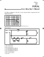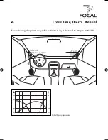
Schéma d'implantation
R1 : 1,2 Ohms / 20 Watts, 5 % céramique
R2 : 8,2 Ohms / 20 Watts, 5 % céramique
R3 : 4,7 Ohms / 20 Watts, 5 % céramique
C1 : 220 µF / 100 V, 10 % condensateur non pôlarisé (noir)
C1_1 : 100 µF / 100 V, 10 % condensateur non pôlarisé (noir)
C2 : 220 µF / 100 V, 10 % condensateur non pôlarisé (noir)
C2_1 : 100 µF / 100 V,10 % condensateur non pôlarisé (noir)
C3 : 8,2 µF / 250 V, 5 % condensateur polypropylène (noir)
C4 : 1 µF / 250 V, 5 % condensateur polypropylène (noir)
C5 : 1 µF / 250 V, 5 % condensateur polypropylène (noir)
L1 : 4 mH self à air, fil Ø 1,00 mm
L2 : 0,27 mH self à air, fil Ø 0,60 mm
L3 : 1 mH self à air, fil Ø 0,85 mm
L4 : 0,16 mH self à air, fil Ø 0,60 mm
S1 : commutateur 2 positions
L1
L2
L3
L4
C4
C5
Switch
Input +
Input -
C1
C1_1
W+
R1
R2
R3
C2
C2_1
C3
W-
T+
T-
M+
M-
15
Notice Cross Uniq
notice cross uniq.indd 15
notice cross uniq.indd 15
4/10/06 14:11:28
4/10/06 14:11:28
Summary of Contents for CROSS UNIQ
Page 18: ......


