Flymaster Vario SD User Manual Download Page 17

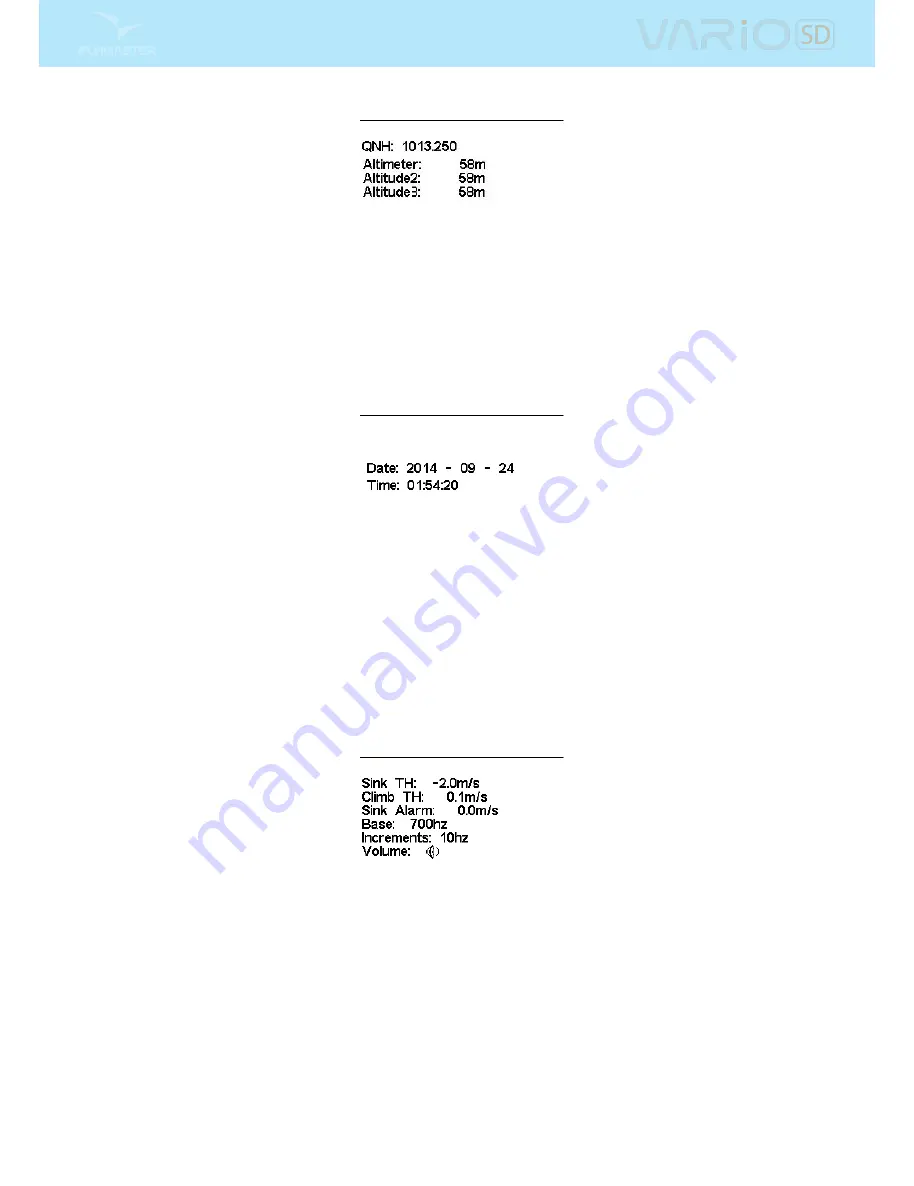
Figure 4.5: Set Altimeter

4.3 Time

The Time page allows the user to set the time, and date. (Figure

4.6

) Time and date values are important

because they are used to classify data in the Flight Log.

Figure 4.6: Timing Parameters

4.4 Vario Acoustics

The Vario Acoustics settings menu option allows the user to change vario sound related parameters. The

user can change the climbing, and sinking rate sound through the respective threshold values. These

thresholds correspond to the climbing and sinking rates at which the sound activates. The user can also

dene in the Acoustic Thresholds option the sink alarm and the sound volume of is the VARIO SD (Figure

4.7

).

Figure 4.7: Vario Acoustics

4.4.1 Climb Threshold

The Climb Threshold denes the rate of climb at which the vario will start beeping. The frequency of the

rst beep is dened trough the

Base Frequency

parameter,and steadily increases according the

Increments

parameter value.

The default value for Climb Threshold is 0.1m/s. This means that beeping starts once the instantaneous

vario value goes above 0.1m/s.

16

All manuals and user guides at all-guides.com

Summary of Contents for Vario SD

Page 1: ...User manual Document version 2 0 All manuals and user guides at all guides com a l l g u i d e s c o m...

Page 2: ...7 3 1 2 Sound 7 3 1 3 Vario 8 3 1 4 Altitude graph 9 3 1 5 Compass 10 3 2 Data eld Elements 11 4 Menu mode 13 4 1 Flight Log 13 4 2 Set Altimeter 15 4 3 Time 16 4 4 Vario Acoustics 16 4 4 1 Climb Thre...

Page 3: ...Settings 20 4 9 RF Probes 21 4 10 Probe Alerts 22 4 11 Calibration 22 5 McCready Functions 24 6 Compass Calibration 25 6 1 Accelerometer Calibration 25 6 2 Magnetometer Calibration 25 7 Firmware 28 2...

Page 4: ...on both the power up screen and the Shutdown menu When the Flymaster VARIO SD is connected to a power supply wall charger or via USB cable even with the unit o the instrument will show if it is being...

Page 5: ...ue on each eld Pushing the ENTER key moves to the next eld or in same cases to the next character digit Conversely pushing MENU key moves to the previous eld or to the previews character digit If the...

Page 6: ...level can be seen using the sound element see Section 3 1 2 for more details Pressing the de ned FS Key will scroll up the sound level until the maximum value Pressing more will mute the sound before...

Page 7: ...ows the user to create an unlimited number of layouts which can be saved to the computer uploaded to the instrument and even shared with other Flymaster users See the Designer user manual available on...

Page 8: ...f the current battery level In Table 3 1 it is possible to see the relationship between what is shown and the actual battery level in percentage This element has xed dimensions Table 3 1 Battery Eleme...

Page 9: ...lement can be resized and re positioned Figure 3 2 Big Analog Vario This Element graphically represents the rate of climb scaled from 0 m s to 10 m s depending if you are climbing or sinking In this E...

Page 10: ...e needle on the analogue dial The maximum and minimum climb rates can be set using the DESIGNER software Figure 3 4 Dial Vario 3 1 4 Altitude graph The Altitude graph element Figure 3 5 corresponds to...

Page 11: ...ass includes an arrow which is always alined with the VARIO SD If the VARIO SD is turned the cardinal points will also turn in order the arrow tip points the right cardinal point Figure 3 8 Compass ex...

Page 12: ...not the instantaneous rate of climb This provides good indication of the quality of the day s thermals This value is reset when the instrument is switched o Max Sink Once a ight has started shows the...

Page 13: ...de ned then this eld will show Dur which in this case is the time elapsed since takeo The takeo event is triggered when ground speed exceeds 5km h and a 3D x is available Alt Gain Loss Altitude Gain L...

Page 14: ...ws to set more of the VARIO SD acoustics see Section 4 5 Screen Allows setting the Screen contrast Language Units Allows setting the interface language and units see Section 4 7 Device Settings Allows...

Page 15: ...ing the ENTER key will display the Flight Log Action List with options Delete ight Delete all ights Each of the options is explained in the following sections Also if you use a ight data download appl...

Page 16: ...s altitude based on atmospheric pressure Since atmospheric pressure can vary sub stantially with meteorological conditions and so with time the barometric altitude also varies according In order to ha...

Page 17: ...correspond to the climbing and sinking rates at which the sound activates The user can also de ne in the Acoustic Thresholds option the sink alarm and the sound volume of is the VARIO SD Figure 4 7 F...

Page 18: ...order to change the base frequency value press the ENTER key after the Audio Frequencies menu option is highlighted This action will highlight the Base Frq value so it can be increased using the UP ke...

Page 19: ...s the climb rate increases This increase in rate is not linear The cadence parameter speci es which cadence curve should be used Current there are 2 possibilities represented in the graph of Figure 4...

Page 20: ...he gure when both pilots enter the thermal nothing is heard The air is rising at 0 1 m s but both pilots are descending at 0 9 m s In the second zone of the thermal the air is rising at 0 8 m s and so...

Page 21: ...O SD interface language and units A short description o the available options for this menu are shown in Table 4 2 The UP and DOWN keys can be used to change each eld option Pushing the ENTER key con...

Page 22: ...ill shows these on the screen see Figure 4 12 Devices are identi ed by their name e g M1 TAS and serial number Devices can be selected using the UP or DOWN keys For the selected highlighted device the...

Page 23: ...ompensation algorithm that ensures accurate compass heading even when the VARIO SD is inclined The Calibration menu option allows the user to calibrate the VARIO SD accelerometer and magnetometer sens...

Page 24: ...rnal factors and the errors are usual negligible for the propose However if you notice strange readings eg G Force value di erent from 1 when the instrument is at rest a calibration should be made The...

Page 25: ...d used to calculate the Speed to Fly is manually set by the pilot McCready Ring On the VARIO SD this value is calculated by averaging the last thermals climbed Conversely for each TAS Speed to Fly val...

Page 26: ...iding moving the VARIO SD 4 The message Calibrating appears on the display for a while and until the calibration is done 5 At the end of the calibration process message Calibration Done appears Figure...

Page 27: ...When the calibration is initiated all the circles are empty no color If the instrument is rotated so that the pitch angle gets close to 90 then the top circle is lled black Similarly if the pitch angl...

Page 28: ...t is correctly made the all the 4 circles will become black and the calibration process automatically stop 4 The end of the calibration process is indicated by the message Calibration Done 27 All manu...

Page 29: ...urther software Figure 7 1 Firmware Menu Option Once the Designer is correctly installed do the following procedure 1 Open the Designer 2 Select Tools Firmware see Figure 7 1 3 Use the new box to choo...

Page 30: ...Figure 7 2 Firmware Update Done 29 All manuals and user guides at all guides com...

Page 31: ...equency 17 Climb Threshold 16 Delete All Flights 15 Delete Flight 14 Increments 17 Sink Alarm 17 Sink Threshold 17 Sound Volume 17 Volume 17 30 All manuals and user guides at all guides com a l l g u...

Reviews: