


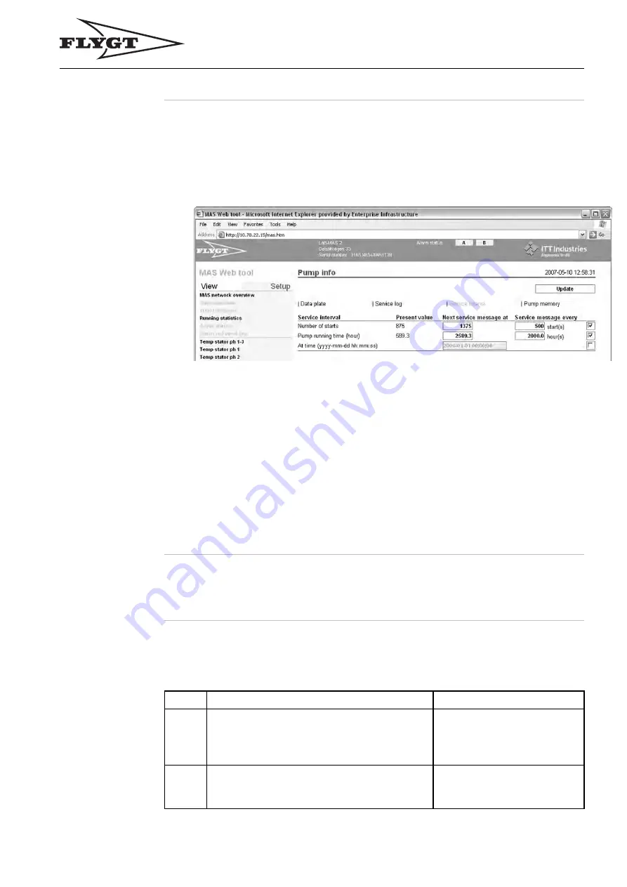
Set Service Interval Using the Operator Panel
Set Service
Interval
Service will be prompted according to the operator’s own settings based on running time,
number of starts or a
fi
xed date.
Follow these steps to set the service interval:
1.
Click Setup – Pump info – Service Interval.
Result:
The Service interval window is opened.
2.
Tick the checkbox to the right of the desired service interval function, to get a
service message at a speci
fi
ed
• number of starts
or
• pump running time (hours)
or
• point of time.
3.
Enter
• the time or number of starts for the next service message (“Next service message at”)
• the interval with which the service messages should recur (“Service message every”)
Note!
For the function At time you only need to enter the time for “Next service
message at”.
4.
Click Update.
Set Service Interval Using the Operator Panel
Instruction
Service will be prompted according to the operator’s own settings based on running time,
number of starts or a
fi
xed date.
Follow these steps to set service interval:
Step
Action
Result/Comment
1
• Go to menu Service interval (2.5.2) using
down arrow and OK.
• Press OK to enter menu At number of
starts (2.5.2.1).
2
If desired, use down arrow to go to menu
• At running time (2.5.2.2)
or
• At date (2.5.2.3).
“Active/Inactive” is displayed
to show if the functions are
activated.
137


