

ATTENTION
37.5x36x10mm
9.5g
Dimensions
3-6S LiPo V B AT
●
Please
don
'
t
flash
any
other
firmware for FC except
“OMNIBUSF4SD”.
●
does
not
need
to set
the
port.
PPM receiver
SBUS
receiver needs to turn on the “Serial RX”
of
UART1
port.
●
SPEKTRUM
●
receiver needs to turn on the “Serial RX” of UART3 port.
_Strip, please
key
in
the
following
codes
on
the CLI
:
●
When
using
LED
key
in
:
“resource led_strip a8 ”
,then
press
the“Enter”
on
the
keyboard.
key in
:
“save”
,
then press the“Enter” on the keyboard.
is any deviation between the detected voltage/current with actual situation, you can adjust the Scale value in the Betaflight-Power&Battery
●
.
If
there
●
5V ,12Vsupply is for low-current use only(5V 1A MAX, 12V 500mA MAX).
bserve polarity at all times
●
O
. Check
and
double
check
before
applying
power
.
●
P
,
in
or
making
any
connections
.
ower off before unplugging plugging
●
K e
m
l
r
.
e p magnets away fro
the F ight Cont oller
●
D
i
o everyth ng you can to prevent vibrations.
Please contact Flycolor sales or technical support for more information.
●
X-Tower F4 FC
06
More
information
●
MCU:
STM32F405.
●
Gyro
MPU-6000 SPI.
:
●
FC firmware:Betaflight_OMNIBUSF4SD
●
Supports PPM,SBUS,SPEKTRUM1024/2048
etc. remote control / receiving mode
.
●
Supports max.32G TF-card, which can record and save more flight/black box data.
●
FC integrated OSD, users can adjust OSD parameters via Betaflight configurator.
●
FC integrated 3.3V,5V, 12V for receiver, VTX, camera, buzzer, LED and other peripheral devices.
●
Provided several silicone cables for FC ,and will give you an unprecedented experience for assembly;
Size
(For reference)
Model
03
Part list / Dimensions
*
All pictures are for reference only
User
Manual
Flight Controller
01
Main features
Operating
Voltage
Weight
(For reference)
Recommend Flycolor X-Tower BL-32 4in1 ESC,Assembly
will be more simple.
04
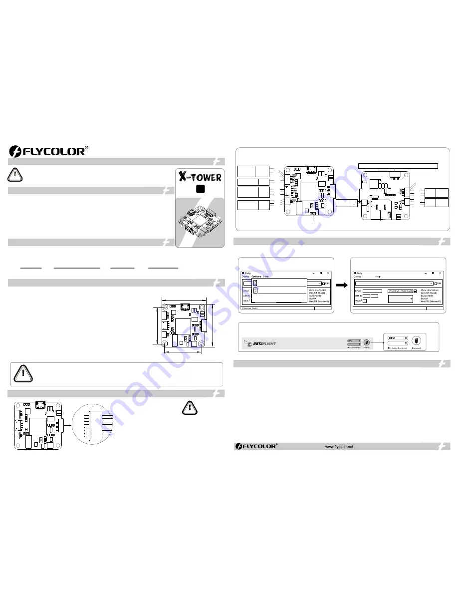
Connect diagram
ATTENTION
●
All welding requires good welding technology, short
circuit between the element or the wire should be
avoided at any time.
●
Please ensure all solder joints are insulated
with heat shrink where necessary.
●
Please double-check the polarity is correct
before power up.
Thank you for using our product. Any Improper operation may cause personal injury damage to the
product and related equipments. This high power system for RC model can be dangerous ,we strongly
recommend reading the user manual carefully and completely. We will not assume any responsibility for any
losses caused by unauthorized modifications to our product. We have the right to change the design,
appearance, performance and usage requirements of the product without notice.
02
Specifications
For quick plug, Flight
Controller
additionally provide
:
●
One
5p
cable (5-pin SH1
.
0
terminal
)
for
SBUS or PPM
receivers
;
●
One 3p cable (3-pin ZH1.5 terminal)for SPEKTEUM receiver;
●
Three 3p cable (3-pin SH1.0 terminal)for different brand VTXs;
●
Two 3p cables (3-pin SH1.0 terminal )for different brand Cameras;
●
One
2p
cables
(
2
-
pin
SH1
.
0
terminal
)
for
Buzzer;
●
One
5p
cables
(
5
-
pin
SH1
.
0
terminal
)
for
LED,S5 and S6;
●
One
6p
cables
(
6
-
pin
SH1
.
0
terminal
)
for
UART3 & UART6.
ATTENTION
●
For these quick plug cables, please confirm the wire sequences on your devices’ connector are corresponding with the Flight
controller’s before connecting. If the terminals are not fit your devices ,please make a modified connection to fit.
●
Please
ensure
all
solder joints
&
wires
are
insulated
well
,
as
short
circuit
will
damage
the
product.
●
Please ensure enough safety space between the ESC& Drone frames, as
short
circuit
will
damage
the
product.
●
Never use this product in harsh environments such as humidity, high temperature, and so on to avoid product damage
You need to use DFU mode to recover firmware for F4 Flight controller, and need a software tool called Zadig to replace the driver for you F.C
when you flash firmware at the first time.
Zadig
2
.
3
.
701
List All Devices
Ignore Hubs or Composite Parents
Create a Catalog File
Sign Catalog&Install Auto generated certificate
Advanced Mode
Log Verbosity
6. Start the “Betaflight ” configurator on the PC;
7
.
Press
and
hold
the
“BOOT”
on the FC
,
connect
the
FC
to
the PC, then the FC is connected in the “DFU” mode, then you can flash the firmware;
8
.
For the
firmware
flashing, you can choose to load the firmware online or local
(
Local
is
recommended, it
needs to download in advance in Betaflight website)
1
.
Start the Zadig
software
tool
;
2
.
Press
and
hold
the
“BOOT”
on the FC
,
connect
the
FC
to
the PC
.
3
.
Click “Options”,and select “List All Devices”.
4
.
Then
select “STM32 BOOTLOADER”,Then click “Replace Driver”
5
.
Close
the
Zadig
software tool
when
replace
successfully,
Then disconnect
the
FC
from
the PC.
(
N
otice
:
If you've run the above steps before, then you don't need to repeat, starting directly from the 6th step
)
CONFIGURATOR
3
.
2
.
2
05
Flash firmware for FC
F11
Zadig
2
.
3
.
701
STM32 BOOTLOADER
STTub30(v3.0.4.0)
0483
D
X
8 devices found
Replace Driver
Options
BOTTOM
TOP
30.5 mm
3
0
.5 m
m
3
6 m
m
37.5 mm
T
F Card
UART6-RX UART6-TX GND 5V UART3-TX UART3-RX
BUZZER
+
S
GND
3.3V
SPEKTRUM
Receiver
Rx3
GND
3.3V
12V
C
amera
GND
12V
Video
SBUS/PPM
Receiver
SBUS/PPM
Vin
GND
5V
GND
SBUS
PPM
TX1
RX1
UART1
TX1
RX1
GND
12V
S
Press the
“BOOT” for flashing firmware
R
X
6
T
X
6
T
X
3
R
X
3
G
N
G
5
V
Video
12V
GND
12V
VTX.
S
12V
GND
LED
5V
GND
LED
strip
LED
5V
GND
S5
S6
Buzzer
F4
Flight controller
G
ND
GND
S1
S2
S3
S4
VBAT
ISA
VBAT
1
#
signal
Vin+
2
#
signal
3
#
signal
4
#
signal
Current
meter
Vin+
251400
-
1098
V1
.
0
F K-X1F4


