

ATTENTION
01
Main features
02
Specification
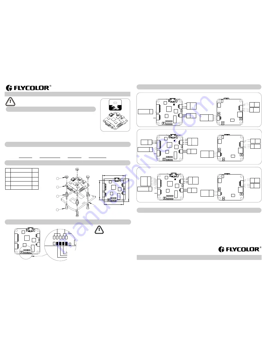
03
Part list / Install Dimensions
04
Wiring Diagram
ATTENTION
05
Receiver modes & Connect method
www.flycolor.net
06
Attention
Install
Dimensions
(
mm
)
User
Manual
Flight Controller
Thank you for purchasing our product. Any Improper operation may cause personal injury damage to the
product and related equipments. This high power system for RC model can be dangerous ,we strongly
recommend reading the user manual carefully and completely. We will not assume any responsibility for any
losses caused by unauthorized modifications to our product. We have the right to change the design,
appearance, performance and usage requirements of the product without notice.
Raptor390
Tower
F3
Flight
Controller
Nylon
spacer M3*5+6
Nylon
Nut M3
Nylon
screw
M3
*
12
1
2
3
4
1
4
4
4
Item
Description
Qty.
*
All pictures are for reference only
●
Only need to connect any one group of VBAT, GND
pads to battery, power supply the FC.
●
Only need to connect the white signal wires on ESC
to S1
-
S4
pads.
●
All welding requires good welding technology, short
circuit between the element or the wire should be
avoided at any time.
●
Please ensure all solder joints are insulated
with heat shrink where necessary.
●
Please double-check the polarity is correct
before power up.
251400-1060,V 1.1
Raptor390 Tower F3 FC
●
Size:36x36x7.5mm; install dimension:30.5x30.5mm,
Φ
3mm
●
Wieght
:
9.5g;
●
Operating Voltage: 7-16V
(
or 2-4S LiPoVBAT
)
;
●
STM32F3
Processor
with
hardware
floating
point
unit
for
efficient
flight
calculations
and
faster
ARM
-
Cortex
M4
core
.
Operation frequence up to 72MHz.
●
Supports
SBUS
,
PPM
,
PWM
etc. receivers
.
●
FC integrated OSD, also integrated 5V, 12V, and battery voltage (VBAT) output, Easy power supply to Image
transmitter, camera, buzzer, LED and other peripheral ;
●
Only
keep
very
simple
connectors
for
flight
,
provides all kind of cables for connectors on FC , to give you an unprecedented experience of installation;
●
Update the FC firmware by connect computer via USB. Full
support
for
OneShot
ESCs
for
easy
PID
tuning
and
a
sharper
response
.
●
Only
need
to
connect
the
single signal
wires
to
the
pads
on
the
flight
controller
PCB
,
easy
to
connect
.
Operating Voltage
Size
( For reference )
Model
F K-D1D1
7-16V Or
2
-
4S
LiPo V B AT
36x36x7.5mm
9.5g
Weight
( For reference )
Recommend Flycolor Raptor390 4in1 ESC. Assembly
will be more simple.
For quick plug, Flight
Controller
additionally provide
::
one
10p
cable (10-pin SH1
.
0
terminal
)
for
PWM
/
PPM
connectors
;
one 3p cable (4-pin SH1.0 terminal)for SBUS connector;
one 6p cable (6-pin SH1.0 terminal)for LED and Buzzer;
three
4p
cables
(
4
-
pin
SH1
.
0
)
for
different brand Image
Transmitters
.
two 3p cables (3-pin SH1.0 )for different brand Cameras;
Attention: For these quick plug cables, please confirm the wire
sequences on your devices’ connector are corresponding with the
Flight controller before connecting. If the terminals are not fit your
devices ,please make a modified connection to fit.
36
36
30.5
30.5
GND S1 S2 S3 S4
VBAT
G
ND
B
O
O
T
GND
S1 S2 S3 S4
GND
VBAT
Battery
V-
Battery V+
4# ESC white signal wire
3# ESC white signal wire
2# ESC white signal wire
1
#
ESC white signal wire
User
Manual
Flight Controller
●
Observe
polarity
at
all
times. Check
and
double
check
before
applying
power
.
●
Power
off
before
unplugging
,
plugging
in
or
making
any
connections
.
●
Connect
only
one
source
of
power
to
the
VCC
pins. Do
not
connect
more
than one
source
of
power
to
two
or
more
of
the
VCC
pins
.
●
The
flight
controller
can
be
powered
by
battery or additional
PDB
.
●
Do
not
connected
GND
,
VCC
to
each
other
(
short
circuit
).
●
Do
not
connect
GND
,
VCC
to
any
inputs
or
outputs
unless
specifically
stated
.
●
Do
not
connect
any
input
or
output
to
any
other
input
or
output
unless
specifically
stated
.
●
5V ,12Vsupply is for low-current use only(5V 1A MAX, 12V 500mA MAX,12V is suggested for camera only).
●
Keep
magnets
away
from
the
Flight
Controller
.
●
Do
everything
you
can
to
prevent
vibrations.
SBUS Mode
BOTTOM
GND
VBAT
GND
S
Buzzer
5V
GND
LED
5V
GND
Image
transmitter
VBAT-
VBAT+
GND
S
L
ED
LED
5V
GND
Buzzer
Buzzer
5V
1
3
5
6
2
PWM
Mode
PPM
Mode
GND
VBAT
GND
S
Buzzer
5V
GND
LED
5V
GND
BOTTOM
Image
transmitter
VBAT-
VBAT+
GND
S
L
ED
LED
5V
GND
Buzzer
Buzzer
5V
1
3
5
6
2
GND
VBAT
GND
S
Buzzer
5V
GND
LED
5V
GND
BOTTOM
L
ED
LED
5V
GND
Buzzer
Buzzer
5V
1
3
5
6
2
Image
transmitter
VBAT-
VBAT+
GND
S
RAPTOR
Flight Controller
390
1
2
3
4
Frame
(
for
reference
)
9
10
GND
5V
CH1
CH2
CH3
CH4
CH5
CH6
AD1
AD2
RX
TX
5V
GND
OSD O UT
12V
GND
PWM
Receiver
GND
5V
CH1
CH2
CH3
CH4
CH5
CH6
1
2
3
4
5
6
7
8
B
O
O
T
GPS
RX
TX
5V
GND
1
2
4
3
TOP
12V
Camera
S
12V
GND
Bridged “BOOT”
for recovering firmware
ISP programming
(OSD Debug)
NC
5V
Reset
RX
TX
GND-
CURRENT METER
RSSI AD2
A D 1
Smart
Port
Pad
S
.P
o
rt
GPS
RX
TX
5V
GND
1
2
4
3
GND
5V
CH1
PPM
Receiver
1
2
3
TOP
RX
TX
5V
GND
S
12V
GND
B
O
O
T
GND
5V
CH1
CH2
CH3
CH4
CH5
CH6
AD1
AD2
12V
Camera
S
12V
GND
Bridged “BOOT”
for recovering firmware
ISP programming
(OSD Debug)
NC
5V
Reset
RX
TX
GND-
9
10
CURRENT METER
RSSI AD2
A D 1
Smart
Port
Pad
S
.P
o
rt
TOP
SBUS
Receiver
RX
5V
GND
1
2
4
GND
5V
CH1
CH2
CH3
CH4
CH5
CH6
AD1
AD2
RX
TX
5V
GND
S
12V
GND
12V
Camera
S
12V
GND
B
O
O
T
Bridged “BOOT”
for recovering firmware
ISP programming
(OSD Debug)
NC
5V
Reset
RX
TX
GND-
9
10
CURRENT METER
RSSI AD2
A D 1
Smart
Port
Pad
S
.P
o
rt


