

05
ESC Programming parameter
www.flycolor.net
251400-1062,V 1.0
06
Attention
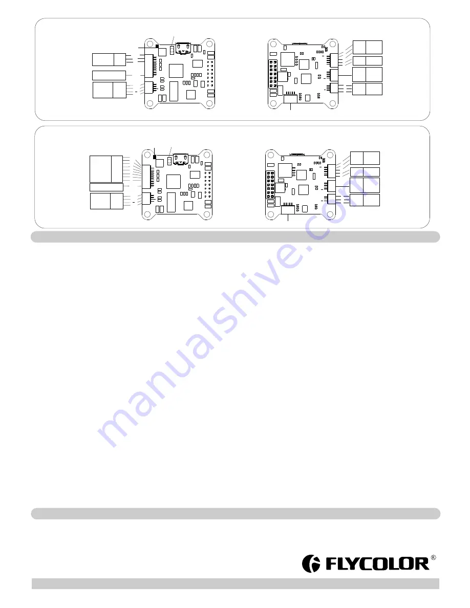
TOP
GND
5V
1
2
3
4
5
6
AD1
AD2
GND
12
V
S
S.Port
B
O
O
T
AD2
RSSI
Video
PPM/PWM
Press
“BOOT” for recovering firmware
Smart
Port
Pad
GND
Vin
GND
VIDEO
GND
12V
S
Image
transmitter
GND
5V
CH1
PPM
Receiver
GND
5V
1
12V
Camera
S
12V
GND
3
2
1
ISP programming
(OSD Debug
)
5V
LED
5V
B
uz-
RX
TX
5V
LED
GND
5V
LED
Buzzer
5V
Buzzer
1
2
3
4
5
S
12V
Camera
SBUS
ISP
T
X
R
X
D
T
R
5
V
G
N
D
BOTTOM
UART3
RX
TX
5V
GND
12V
Camera
S
12V
GND
3
2
1
ISP programming
(OSD Debug
)
5V
LED
5V
B
uz-
RX
TX
5V
LED
GND
5V
LED
Buzzer
5V
Buzzer
1
2
3
4
5
S
12V
Camera
SBUS
ISP
T
X
R
X
D
T
R
5
V
G
N
D
BOTTOM
UART3
RX
TX
5V
GND
TOP
GND
5V
1
2
3
4
5
6
AD1
AD2
GND
12
V
S
S.Port
B
O
O
T
Video
PPM/PWM
Press
“BOOT” for recovering firmware
Smart
Port
Pad
GND
Vin
GND
VIDEO
GND
12V
S
Image
transmitter
PWM
Receiver
GND
5V
CH1
CH2
CH3
CH4
CH5
CH6
GND
5V
1
2
3
4
5
6
AD2
RSSI
PPM Mode
PWM Mode
1. Startup power:
Startup power can be set to relative values from 0.031 to 1.5. This is the maximum power that is allowed during startup. Actual applied power depends on throttle input, and
can be lower, but the minimum level is a quarter of the maximum level. Startup power also affects bidirectional operation, as the parameter is used to limit the power applied
during direction reversal. For low rpms, the maximum power to the motor is limited, in order to facilitate detection of low BEMF voltages. The maximum power allowed can be
set via the startup power parameter.
2.
Commutation timing:
Commutation timing can be set to low/mediumlow/medium/mediumhigh/high, that correspond to 0
°
/7.5
°
/15
°
/22.5
°
/30
°
timing advance.
Typically a medium setting will work fine, but if the motor stutters it can be beneficial to change timing. Some motors with high inductance can have a very long commutation
demagnetization time. This can result in motor stop or stutter upon quick throttle increase, particularly when running at a low rpm. Setting timing to high will allow more time for
demagnetization, and often helps.
3. Demag compensation:
Demag compensation is a feature to protect from motor stalls caused by long winding demagnetization time after commutation. The typical symptom is motor stop or stutter
upon quick throttle increase, particularly when running at a low rpm. As mentioned above, setting high commutation timing normally helps, but at the cost of efficiency.
Generally, a higher value of the compensation parameter gives better protection. If demag compensation is set too high, maximum power can be somewhat reduced.
4. Direction:
Rotation direction can be set to fwd/rev/bidirectional fwd/bidirectional rev. In bidirectional mode, center throttle is zero and above is fwd rotation and below is reverse rotation.
When bidirectional operation is selected, programming by TX is disabled.
5. Beep strength:
Sets the strength of beeps under normal operation.
6. Beacon strength:
Sets the strength of beeps when beeping beacon beeps. The ESC will start beeping beacon beeps if the throttle signal has been zero for a given time. Note that setting a high
beacon strength can cause hot motors or ESCs!
7. Beacon delay:
Beacon delay sets the delay before beacon beeping starts.
8. Programming by TX
: If disabled, throttle calibration is disabled.
Please notice that throttle stick can calibrate throttle range only, and can not programming paramenter via throttle stick .
9. Min throttle, max throttle and center throttle:
These settings set the throttle range of the ESC. Center throttle is only used for bidirectional operation. The values given for these settings are for a normal 1000us to 2000us
input signal, and for the other input signals, the values must be scaled.
10.Thermal protection:
Thermal protection can be enabled or disabled. And the temperature threshold can be programmed between 80
°
C and 140
°
C
(
from
rev16
.
3
)
.
The ESC measures temperature within the MCU and limits motor power if the temperature is too high. Motor power is limited in four steps:
- If the temperature is above threshold , motor power is limited to 75%.
- If the temperature is above threshold 5
°
C, motor power is limited to 50%.
- If the temperature is above threshold 10
°
C, motor power is limited to 25%.
- If the temperature is above threshold 15
°
C, motor power is limited to 0%.
11.Low RPM power protect:
Power limiting for low RPMs can be enabled or disabled. Disabling it can be necessary in order to achieve full power on some low kV motors running on a low supply voltage.
However, disabling it increases the risk of sync loss, with the possibility of toasting motor or ESC.
12.Brake on stop:
Brake on stop can be enabled or disabled. When enabled, brake will be applied when throttle is zero. For nonzero throttle, this setting has no effect.
Programming parameters below can be accessed from the configuration software (BLHeliSuite):
●
User need to calibrate the throttle range when starting to use a new ESC or another transmitter. When
the
input
signal
is
Dshot
,
throttle
calibration
is
disabled
●
BLHeli-S open-source firmware, when some abnormality occurs in ESC driving the motor or need the motor to reach a higher RPM, user can try to change the timing.
●
Observe
polarity
at
all
times. Check
and
double
check
before
applying
power
. ●
Power
off
before
unplugging
,
plugging
in
or
making
any
connections
.
●
5V ,12Vsupply is for low-current use only(5V 1A MAX, 12V 500mA MAX).
●
Keep
magnets
away
from
the
Flight
Controller
.
●
Do
everything
you
can
to
prevent
vibrations.
●
Please contact Flycolor sales or technical support for more information.
User
Manual
Multi
-
Rotor
Brushless
ESC


