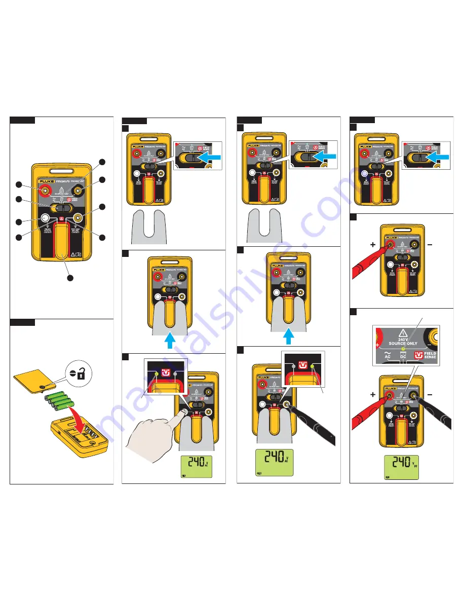
Figure 4
2
1
3
LED
8
7
9
4
5
6
Figure 1
Figure 2
Figure 3
Figure 5
All manuals and user guides at all-guides.com
Page 1: ...e the switch to the AC or DC position See Figure 5 2 Place the red test lead from the test tool into the terminal and press down firmly 3 Place the black test lead from the test tool into the terminal...
Page 2: ...Figure 4 2 1 3 LED 1 8 7 9 2 3 4 5 6 Figure 1 Figure 2 Figure 3 2 1 3 LED Figure 5 2 1 3 LED All manuals and user guides at all guides com...