9100A-017
7-18
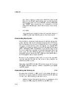
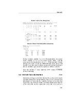
results are not stable, the
setoffset
command should be used to
delay the data read with respect to the clock. An alternative
method would be to add one more vector to hold RD and CE low
while the capture is performed before returning RD and CE
high.
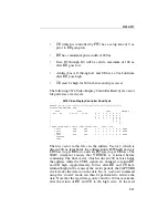
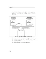
Once the controller read and write cycles have been determined,
a vector file to control and test the controller can be written by
changing the address and data fields as appropriate. By changing
PS7 and PS6 and adding UDS to follow the LDS pattern, the
write cycle to access the video RAM can be made. Vector files
can then be built that display various patterns that can be used to
test the video board
WAIT APPLICATION
7.17.
The edge specified for the WAIT command in a vector file
cannot be changed within the vector file. For some handshaking
protocol, it may be necessary to wait for an edge of one polarity,
drive some vectors, and wait for the edge of the other polarity.
This can be performed externally to the module by dedicating
one of the output lines of the module to control an exclusive OR
gate to be used as a programmable inverter. The vector file
entries for the dedicated line determine if the event connected to
the other input of the gate should be inverted (or not inverted)
before going to the WAIT input of the module.
In some applications, WAIT may need to be checked for a level
rather than an edge (for example, checking for clear-to-send
(CTS) or BUSY signals). The external ENABLE line could be
used to perform this function only if the application does not re-
quire programmable checks and does not have problems if vec-
tor driving is stopped during a particular series of vectors. If
neither of these conditions can be met, there are several different
methods that could be used to check for a level.
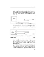
One method would dedicate a line from the Vector Output I/O
Module for a gate on a test fixture that enables the controlling
signal (CTS, etc.)(see Figure 7-3). The vector immediately pre-
ceding the WAIT statement in the vector file would contain a
level that enables the controlling signal. When the vector was
driven and the controlling signal was at the desired level, setting
Summary of Contents for 9100A Series
Page 6: ...vi ...
Page 8: ...viii ...
Page 10: ...x ...
Page 14: ...9100A 017 1 4 ...
Page 24: ...9100A 017 3 6 ...
Page 44: ...9100A 017 5 4 ...
Page 58: ...9100A 017 6 14 ...
Page 83: ...A 1 Appendix A New TL 1 Commands ...
Page 84: ...9100A 017 A 2 ...
Page 87: ...clockfreq 3 For More Information The Overview Of TL 1 section of the Programmer s Manual ...
Page 88: ...clockfreq 4 ...
Page 91: ...drivepoll 3 For More Information The Overview Of TL 1 section of the Programmer s Manual ...
Page 92: ...drivepoll 4 ...
Page 104: ...vectordrive 4 ...
Page 107: ...vectorload 3 For More Information The Overview Of TL 1 section of the Programmer s Manual ...
Page 108: ...vectorload 4 ...
Page 116: ...9100A 017 C 2 ...
Page 117: ...9100A 017 C 3 ...
Page 118: ...9100A 017 C 4 ...

