background image

1750 

Operators Manual 

30 

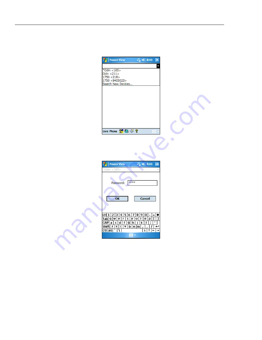
If more than one Recorder is within range, the Recorder selection screen appears. An 

asterisk preceding the Recorder name means that unit is password protected. If your 

recorder is not listed, but in range, press "Search New Devices" to update the list. 


Azd113.bmp 

If the selected Recorder is not password protected, the Home screen appears. If password 

protection is set, the Password screen appears instead.  


Azd114.bmp 


Summary of Contents for 1750

Page 1: ...Recorder Operators Manual October 2006 Rev 3 11 10 2006 2010 Fluke Corporation All rights reserved Specifications are subject to change without notice All product names are trademarks of their respective companies ...

Page 2: ...rvice center to obtain return authorization information then send the product to that service center with a description of the difficulty postage and insurance prepaid FOB Destination Fluke assumes no risk for damage in transit Following warranty repair the product will be returned to Buyer transportation prepaid FOB Destination If Fluke determines that failure was caused by neglect misuse contami...

Page 3: ...the Power Recorder at a Facility 11 Work Flow 11 Installing the Recorder 12 Connecting the Recorder to the Wiring 12 Verifying Your Connection 13 Finishing UP 13 Managing Recorded Data 14 Power Type Diagrams 14 Communicating with the Recorder Using Power View 25 Navigating in Power View on the PDA 26 Power View Menus 26 Icons on the Menu Bar 27 Menu Tree 28 Home Screen 29 Downloading Data and Eras...

Page 4: ...with Annotations 45 Using Image or Voice Annotations 47 Inserting Image or Voice Annotations 47 Turn off the Recorder 48 Cleaning and Maintenance 48 Regulatory Information for Wireless Communication 49 Specifications for the System Recorder and Power Analyze Software 50 General Specifications 50 Input Specifications 50 Synchronization and Sampling 50 Voltage and Current Measurements 50 Voltage and...

Page 5: ...iii List of Tables Table Title Page 1 Symbols 4 2 Standard Accessories 4 3 Input Terminals and Controls 6 ...

Page 6: ...1750 Operators Manual iv ...

Page 7: ...ental Ground Terminal 8 4 One Phase Plus Neutral 15 5 One Phase IT No Neutral 16 6 One Phase Split Phase 17 7 Three Phase Wye 18 8 Three Phase Delta 19 9 Three Phase IT 20 10 Three Phase High Leg 21 11 Three Phase Open Leg 22 12 2 Element Delta 23 13 2 Element Wye 24 14 Connecting to the Recorder 25 15 Power View Menu Tree 28 ...

Page 8: ...1750 Operators Manual vi ...

Page 9: ...A The range of the PDA with the wireless link is about 5 meters 16 feet from the Recorder This range is dependent on the electrical interference in the location Simplified test lead connections to the power network Simply connect a voltage probe to a conductor on each phase that you want to record On the current inputs the Recorder automatically identifies what type of probe is connected The Recor...

Page 10: ...y Should you want to extensively analyze collected data the procedures described later in this manual review the transfer of data from the Recorder to the PDA and finally to a PC Data may then be analyzed using Power Analyze on a PC Extensive online help is provided in the Power Analyze software on the product CD shipped with the Recorder Contacting Fluke To contact Fluke call one of the following...

Page 11: ...terminals Remove all probes test leads and accessories that are not necessary for the measurement Make sure the ground conductor in the mains power cord is connected to a protective earth ground Disruption of the protective earth could put voltage on the chassis that could cause death Only use probes test leads and accessories that have the same measurement category voltage and amperage ratings as...

Page 12: ...inst transients from the primary supply level such as an electricity meter or an overhead or underground utility service Accessories Table 2 describes the standard accessories that ship with the Recorder Table 2 Standard Accessories Description Part Number Ethernet cable 3 meters yellow 2402854 Colored plastic clips for test leads 32 clips 8 colors 4 clips each color 2157607 Model TLS430 test lead...

Page 13: ...amp on Current Transformers 3005R Flexible Current Transformers 3110 3210 3310 3312 Interface and Extension Cables 3570 CT Cable Features The Recorder front panel is illustrated in Figure 1 and described in Table 3 SD ETHERNET POWER 1750 POWER RECORDER ON BUSY LINK 100 240 V 47 63Hz B A C N VOLTAGE CURRENT 4 13 1 2 3 11 10 8 12 7 5 6 9 azd09f eps Figure 1 Fluke 1750 Power Recorder WCaution Connect...

Page 14: ...order when not using the PDA This is the recommended method of data transfer due to its speed and reliability H Busy Indicator Blinking Network is busy I Link indicator Off No link Steady Link Present Blinking Communicating with PC J Current Measurement Terminals 5 K Current indicator Steady Current probe in normal range Blinking 110 of probe range use a higher range probe Off Current insufficient...

Page 15: ...the decal appropriate for your local wiring codes around the current and voltage inputs as shown in Figure 2 EUROPE UK new std L2 L2 L1 L1 N VOLTAGE CURRENT China B A C N N VOLTAGE CURRENT EU old std L2 L2 L1 L1 L3 L3 N VOLTAGE CURRENT UK L2 L1 L3 N VOLTAGE CURRENT USA B A C N VOLTAGE CURRENT Canada CURRENT B A C N VOLTAGE SD ETHERNET POWER 1750 POWER RECORDER ON BUSY LINK 100 240 V 47 63Hz B A C ...

Page 16: ...eates a ground loop that can damage the Recorder Potential Ground Loop Correct No Ground Loop Optional Protective Chassis Ground See detail below Different Power System OK Line Power Cord Power Network Being Measured See Caution Above Incorrect Creates Ground Loop GND N ØC ØB ØA azd11f eps Figure 3 Connecting the Supplemental Ground Terminal ...

Page 17: ...as been registered you will receive email notifications of firmware and software update availability Installing Power View on the PDA 1 Insert the CD that ships with your PDA Follow the on screen instructions to install the ActiveSync software for Windows XP or Mobile Device Center for Windows Vista and Windows 7 that allows your PC to communicate with the PDA 2 Connect the PDA to your PC with the...

Page 18: ...dows XP Windows Vista 32 64bit Windows 7 32 64bit Administrator privileges are required to install applications PC with 500 MHz or faster processor 256 MB RAM 1 GB recommended 100 MB of available disk space 10 GB recommended 1024 x 768 or higher resolution video Keyboard and mouse Installing Power Analyze Before installing the software on your PC make sure you have Internet Explorer version 6 or l...

Page 19: ... may need to change your Windows firewall settings to allow the program FPA exe to use ports 18571 TCP and 18572 UDP For more on changing firewall settings refer to http support microsoft com Installing the Power Recorder at a Facility This section describes the steps you need to take to set up the Recorder at a facility and begin a recording session Work Flow There are three distinct stages for a...

Page 20: ...may need to select Browse for recorder when first connecting Select the recorder you want to browse to with the PDA stylus Upon selection the Home screen for live data appears If more than one Recorder is within range these will appear in the drop down menu list 6 If you have previously established password protection for the Recorder you must type the correct password in the Password text box and...

Page 21: ...uld be attached to the same phase wire or busbar 7 Check the LED for each phase to make sure a connection is established When a phase LED is ON or lighted you know that the connection is active and that voltage and current is within the normal range When a phase LED is BLINKING you are connected but the voltage or current is exceeding the normal range or exceeding the range of the probe that you a...

Page 22: ...reasons or if you want to simplify what you will be seeing in the download data screen The start and end times will represent one recording session when old data is erased Note Data is not removed from internal Recorder memory until you erase it using Power View software on the PDA or Power Analyze software on your PC Power Type Diagrams The wiring illustrations included cover the standard power c...

Page 23: ...r Type Diagrams 15 SD ETHERNET POWER 1750 POWER RECORDER ON BUSY LINK 100 240 V 47 63Hz B A C N VOLTAGE CURRENT A L1 N GND GND N ØA L1 Source azd02f eps Figure 4 One Phase Plus Neutral Example Branch circuit at an outlet ...

Page 24: ... POWER 1750 POWER RECORDER ON BUSY LINK 100 240 V 47 63Hz B A C N VOLTAGE CURRENT A L1 GND GND B L2 azd14f eps Figure 5 One Phase IT No Neutral Example Used in Norway and in some hospitals This would be the connection at a branch circuit ...

Page 25: ...rams 17 SD ETHERNET POWER 1750 POWER RECORDER ON BUSY LINK 100 240 V 47 63Hz B A C N VOLTAGE CURRENT A L1 N GND B L2 azd03f eps Figure 6 One Phase Split Phase Example A North American residential installation at the service entrance ...

Page 26: ... 1750 POWER RECORDER ON BUSY LINK 100 240 V 47 63Hz B A C N VOLTAGE CURRENT B L2 A L1 C L3 N GND Source GND ØC L3 ØA L1 ØB L2 azd04f eps Figure 7 Three Phase Wye Example Also called Star or four wire connection Typical commercial building power ...

Page 27: ...ETHERNET POWER 1750 POWER RECORDER ON BUSY LINK 100 240 V 47 63Hz B A C N VOLTAGE CURRENT GND ØA L1 B L2 C L3 A L1 GND ØC L3 ØB L2 azd05f eps Figure 8 Three Phase Delta Example Often found in industrial settings where electric motors are used ...

Page 28: ...R 1750 POWER RECORDER ON BUSY LINK 100 240 V 47 63Hz B A C N VOLTAGE CURRENT GND ØA B L2 C L3 A L1 GND ØC L3 ØB L2 L1 azd12f eps Figure 9 Three Phase IT Example Industrial power in countries that use the IT Isolated Terra system such as Norway ...

Page 29: ...50 POWER RECORDER ON BUSY LINK 100 240 V 47 63Hz B A C N VOLTAGE CURRENT GND ØC L3 A L1 B L2 C L3 N GND ØB L2 ØA L1 azd08f eps Figure 10 Three Phase High Leg Example A way to get a 120 V single phase feed by tapping across part of a leg in a delta power system ...

Page 30: ...SD ETHERNET POWER 1750 POWER RECORDER ON BUSY LINK 100 240 V 47 63Hz B A C N VOLTAGE CURRENT GND ØA L1 B L2 C L3 A L1 GND ØC L3 ØB L2 azd18f eps Figure 11 Three Phase Open Leg Example A variant of power transformer winding type ...

Page 31: ...OWER 1750 POWER RECORDER ON BUSY LINK 100 240 V 47 63Hz B A C N VOLTAGE CURRENT GND ØB L2 C L3 A L1 GND B L2 ØA L1 ØC L3 azd13f eps Figure 12 2 Element Delta Example Blondel or Aron connection used to measure power like a two element revenue power meter ...

Page 32: ...0 POWER RECORDE R ON B US Y LINK 100 240 V 47 63Hz B A C N VOLT AGE CURRENT B L2 No Connection to 1750 voltage input C L3 A L1 N GND ØB L2 ØC L3 ØA L1 azd07f eps Figure 13 2 Element Wye Example Blondel or Aron system for 4 wire Wye power secondaries ...

Page 33: ...a monitoring session You can alternatively connect to a Recorder from a PC directly using an Ethernet cable or remotely over an IP network You can then use Fluke Power Analyze to set up the Recorder view power measurements wherever the Recorder is installed or download data from the Recorder Power View communicates with the PDA using a wireless controller radio interface There is no provision for ...

Page 34: ...vailable by tapping the sector of interest or the Live menu Once a detail view is selected navigation to all available detail views is accomplished using the Live menu Menu Brings up the Data memory management screens which are for download to the SD card inserted in the Recorder and for erasing Recorder internal memory and erasing SD card files 1750 Setup Brings up the setup screen that allows yo...

Page 35: ...ou want to display The Snapshot icon triggers the Recorder to capture high resolution waveform data and save it in the recorded data stream This waveform capture is identical to the snapshots taken automatically when you set the snapshot period in the 1750 Setup menu This icon brings up the Annotate screen Use the annotate menu to enter text or to insert a file name and load it into the recorded d...

Page 36: ...ry Card Full If Memory is full Download SD Card Files Phasor Annotate Memory Data Settings Check List Harmonics Trend Snapshot Interval 1750 Internal Memory 1750 SD Memo Write to SD Delete File Cancel 1750 Memory Card Files Delete File Return to Download Cancel Erase All 1750 Setup Setup Password Incorrect Password Connecting 1750 Power Recorder Not Found 1750 Power Recorders Found Erase 1750 Memo...

Page 37: ...e and then Home on the Menu Bar The Home screen contains a 1 5 cycle waveform screen a digital meter screen and a PHASOR screen The parameters shown in this screen are not configurable All phases are shown simultaneously either all voltage or all current Azd111 bmp If no Recorders are within range the following screen appears Azd112 bmp ...

Page 38: ... preceding the Recorder name means that unit is password protected If your recorder is not listed but in range press Search New Devices to update the list Azd113 bmp If the selected Recorder is not password protected the Home screen appears If password protection is set the Password screen appears instead Azd114 bmp ...

Page 39: ...nternal Memory in the Data menu to view the Download screen Azd116 bmp The Download screen shows a three phase rms V strip chart with date and timescale shown This represents the data in the Recorder internal memory The default settings of the start and stop times is everything in memory To download ALL tap the Write to SD button If you want to trim off data that contains partial information becau...

Page 40: ...ata files it may not have room for the new download Power View alerts you to this condition and asks if you would like to erase the SD card before downloading Azd107s bmp You can also access the SD card to delete files by selecting Tools 1750 SD Memory from the Data menu option ...

Page 41: ...ard a message confirming the download will appear Azd118 bmp You can also tap the Erase 1750 Memory from the Data menu option which is available under Menu and tap the Erase All button to erase all power quality data stored in the Recorder Even then if you want you can leave old data in Recorder memory It will be overwritten automatically when you start your next Recorder session so it never has a...

Page 42: ...p caution Are you sure appears on the screen Azd119 bmp Note You can also download data by connecting your PC directly to the Recorder with an Ethernet cable and run Power Analyze in the 1750 Live mode All of the functions controller PDA and Power View are duplicated in 1750 Live mode ...

Page 43: ...data on the circuits on the circuits for example Scope Meter Phasor or Harmonics Azd120 bmp Scope Screen The Scope screen shows 1 5 cycle waveform data for the volts and amp lines selected in the check boxes on Phase View screen Tap the Phase icon to display the Phase View screen Azd121 bmp ...

Page 44: ...n use the V and A arrows on the upper right of the screen to change the scaling of voltage and current on the PHASOR diagram You can easily correct an erroneous Recorder connection by going directly to Menu 1750 Setup Phase Swap and using the Recorder to internally invert a CT swap a voltage or CT phase or modify a scaling parameter then return to the screen to verify that the correction has been ...

Page 45: ...zed European labeling scheme If the power type is Wye V phases are AN BN CN and NG N neutral G ground Azd124 bmp Trend Screen The Trend screen shows live data being recorded as a strip chart display of the selected phases of voltage or current This moment in time is visible on the right side of the graph The traces fill the screen in 10 minutes and continue FIFO first in first out This feature is ...

Page 46: ...ne selection menu is available using the button at the bottom The Phase Selection screen reveals check boxes for selecting the voltage and current channels you want to display Azd126 bmp Setting Up the Recorder To adjust the settings of the Recorder tap Menu 1750 Setup Azd127 bmp ...

Page 47: ...the Setup screen you can adjust either the recording period information or the Recorder settings Tap an icon on the Setup screen to view or configure Clock Probe Detect IP Address Measurement Description Nominal Power Phase Swap Volts Current Ratio Recorder Name Password Snapshot Period Language ...

Page 48: ...e this feature to set the PDA clock or clock to synchronize the Recorder with the PDA clock Azd128 bpm Probe Detect This screen shows the types of probes attached to the Recorder current inputs Current probes are automatically detected azd129 bmp ...

Page 49: ...cription Click on the arrow and select one of the six available captions from the list box and enter the text in the text field below The number of characters is limited to 50 Click on Insert to apply the changes You may change or delete the caption The maximum possible length for caption text is 20 characters To apply changes click on Apply Click OK to close the window and send the measurement de...

Page 50: ...ltage levels may be entered if required Azd131 bmp Using Phase Swap Rather than having to change the physical connections to the power system use the Phase Swap feature to make a software selectable correction without physically switching the cable You can select from the following Swap any voltage input Swap any current input Invert any current input clamp The screen shows check boxes to invert a...

Page 51: ...ratio applies a ratio to the current input in order to show the current present on a medium voltage network This feature is intended to be used for sensing low levels of current to represent the much higher levels on the primary side at a substation or step down transformer that has built in metering current transformers Azd134 bmp Assign Recorder Name and Password Use this feature to assign a nam...

Page 52: ...e recorded data stream These snapshots contain a phasor diagram waveforms of current and voltage harmonics profiles and other data None 10 minutes 30 minutes 1 hour Note You can take a snapshot manually at any time at any time while connected over the wireless link to a Recorder Press the Waveform icon on any of the View screens to take a snapshot The message Snapshot Acquired confirms that a snap...

Page 53: ...ian Select one of these languages and select your preference of phase identifier as A B C or L1 L2 L3 A restart of Power View is required to apply these changes azd142 bmp Working with Annotations Annotations are optional markers that can be inserted by the Recorder operator to flag a particular point in the data when recording They are usually inserted on using Power View with the wireless PDA ...

Page 54: ...nnotation yellow File annotations contain the name of a picture or audio file relevant to the data See Using Image or Voice Annotations later in this manual Text annotation Text annotations contain a text note Power Configuration Change annotation Power Configuration Change annotations are inserted by the system when a change is made to the Power Configuration in the Recorder These markers only di...

Page 55: ...ile you are monitoring data with a Recorder you may find it helpful to take a picture that relates to the power quality data you are recording or to record verbal comments as you observe the conditions or review the data being measured You can then associate the image or recording with the data being recorded by adding annotations that reference them The PDA includes a microphone for recording not...

Page 56: ...Recorder for transport you have the option to shut down the Recorder and disable the UPS before unplugging the power cord To turn off the Recorder 1 Select Menu Tools 1750 Shut down 2 Confirm the warning message 3 Wait until the Power LED is solid green The power cord can be safely unplugged azd143 bmp Cleaning and Maintenance The Recorder contains no user serviceable parts Contact an Authorized F...

Page 57: ...ovide reasonable protection against harmful interference when the equipment is operated in a commercial environment This equipment generates uses and can radiate radio frequency energy and if not installed and used in accordance with the instruction manual may cause harmful interference to radio communications Operation of this equipment in a residential area is likely to cause harmful interferenc...

Page 58: ... Channels Voltage 5 channels AC DC Current 5 channels Voltage Channels Input resistance 2 MΩ Input capacitance 20 pF Current Channels Self identifying probes Types available current clamps Flexi CTs Measuring Method Simultaneous digital sampling of voltage and current Digital PLL synchronized sampling internal frequency reference used during voltage drops Synchronization and Sampling PLL Synchroni...

Page 59: ...cale 8000 V pk Sample Resolution 200 nS Measurement Uncertainty 5 reading 20 V test parameters 1000 V dc 1000 V rms 100 kHz Dip Sag and Swell Measurements Voltage Swell rms swell Measurement Type True rms one cycle calculation by overlapping each half cycle voltage between lines is measured for 3P3W lines and phase voltage is measured for 3P4W lines Displayed Data Amplitude and duration of swell M...

Page 60: ...4 7 2002 Voltage flicker Measurement Method as per IEC 61000 4 15 2003 10 min Pst 2 h Plt External Interface Specifications LAN Interface Connector RJ 45 Speed and Type 10 100 Base T auto MDIX Communications Protocol TCP IP over Ethernet Wireless Controller Interface Connection wireless 2 4 GHz radio Speed up to 700 kbit second Communications Protocol Bluetooth SPP Environmental and Safety Specifi...

Reviews: