Electrical Safety Analyzer
Turning the Analyzer On
Turning the Analyzer On
Note
To ensure the high voltage indicator is working,
look for it to illuminate during the power-up self
test.
Press the power switch on the rear panel so the “I” side of
the ac power switch is depressed. The Analyzer will
perform a series of self tests and then display the
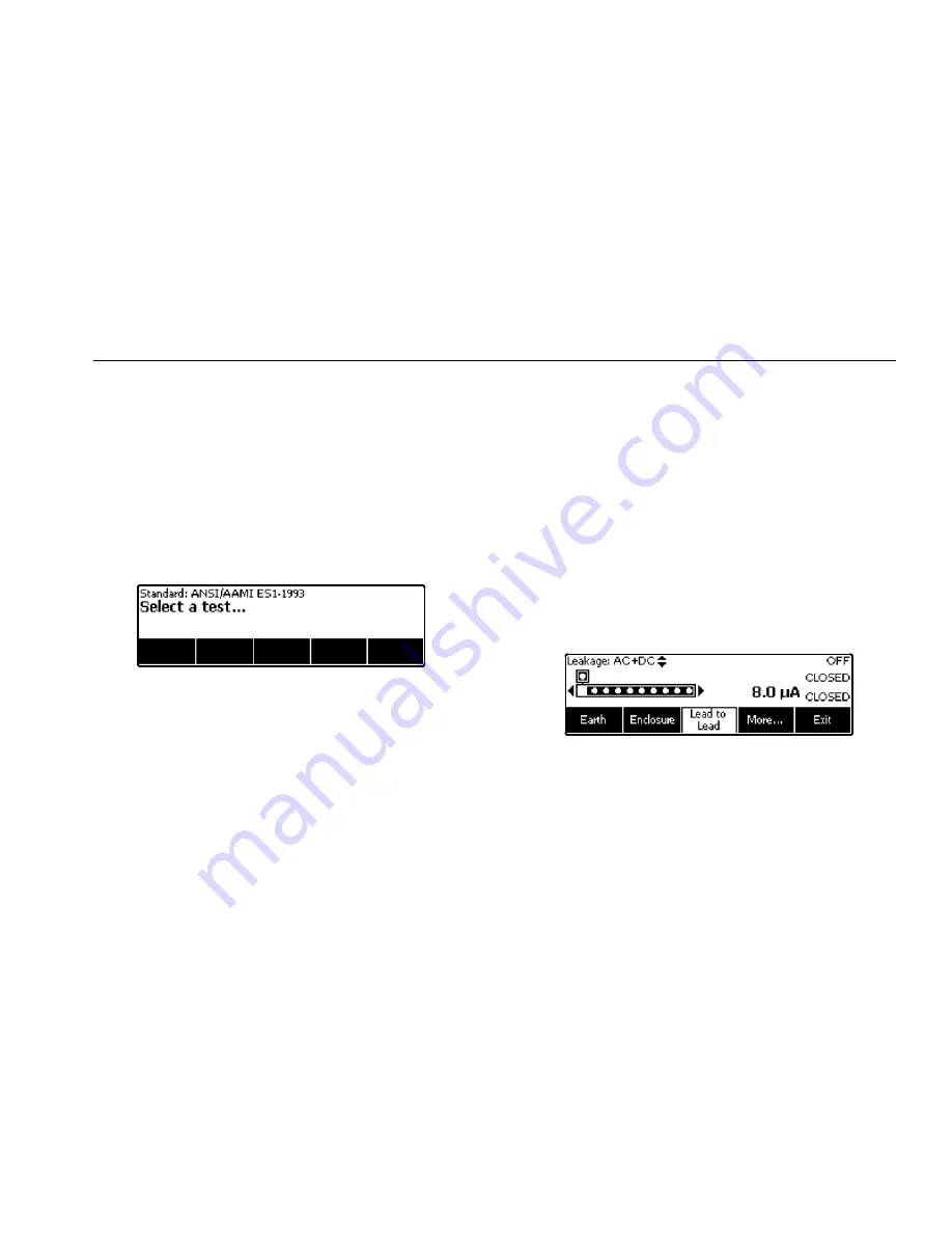
message shown in Figure 4 when the self test has
completed successfully.
faw05.eps
Figure 4. Analyzer Ready for Operation
During the self-test, the Analyzer checks its ac mains
input for proper polarity, ground integrity and voltage
level. The high voltage indicator illuminates briefly during
the self test. If the polarity is reversed, the Analyzer
indicates this condition and allows the polarity to be
reversed internally. If the ground is open, the Analyzer
displays this fault. If the mains voltage is too high or too
low, the Analyzer displays this fault and does not continue
until the supply voltage is corrected and the ESA620
power cycled off and then on again.
Adjusting the Display’s Contrast
While the Analyzer displays the start-up menu shown in
figure 4, press
or
to increase or decrease the
display’s contrast. Press the softkey labeled
Done
to exit
contrast setup.
Accessing the Analyzer’s Functions
For each test and setup function, the Analyzer uses a
series of menus to access various Analyzer tests and
setup variables. As shown in Figure 5, the Analyzer
indicates various leakage current tests along the bottom
of the display. An Exit selection is also indicated as a way
of backing out of the leakage current tests. Pressing a
softkey (F1 through F5) under a specific test will cause
the analyzer to setup for or perform the selected test.
faw04.eps
Figure 5. Leakage Current Menu
11
Summary of Contents for ESA620
Page 6: ......
Page 8: ...ESA620 Getting Started Manual Specifications 17 Detailed Specifications 18 ii ...
Page 10: ...ESA620 Getting Started Manual iv ...
Page 12: ...ESA620 Getting Started Manual vi ...
Page 22: ...ESA620 Getting Started Manual faw03 eps Figure 3 DUT Connections to the Analyzer 10 ...


