17
6.1 General
Before starting installation, inspect the di-
gital positioner for any transit damages.
The
PMV D20
positioner is installed with a
mounting kit (according to NAMUR
specification) to the left-hand actuator sup-
port rod.
Generally, the unit can be installed in any
mounting position. The stroke feed-back
is realized by a follower arm and stem
clamps.
The mounting of rod actuators (according
to NAMUR) is described in Figure 3.
For the two mounting possibilities of cast
yoke actuators (according to NAMUR, lEC
534 part 6) refer to Figure 5.
After installation, ensure all screw
connections are tightened correctly and
all moving parts are free from excessive
friction.
6. Mounting and installation
6.2 Mounting of the PMV D20
positioner on a linear
pneumatic actuator
(NAMUR / IEC 534 part 6)
(See Figure 3)
The mounting of a rod actuator kit
(according to IEC 534 part 6) is described
in an example by using the following
equipment:
Valve:
Standard globe valve or
equivalent
Actuator:
Single-acting pneumatic
actuator
Positioner:
PMV D20
with NAMUR
mounting kit
Pre-assembly: Valve with actuator (valve
stroke is matched with the actuator
stroke).
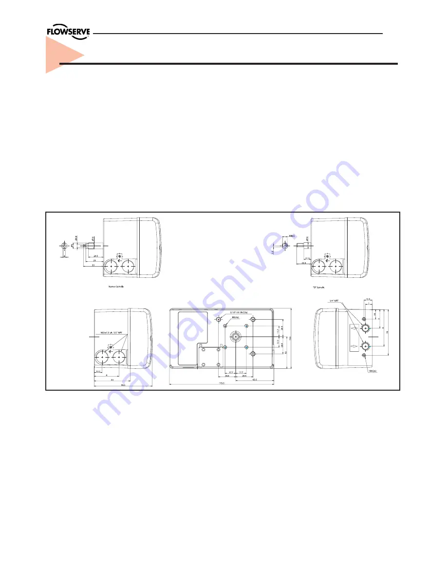
Figure 2. Dimensional drawing
Summary of Contents for PMV D20
Page 1: ...Installation Operation Maintenance PMV D20 Digital Positioner ...
Page 11: ...11 4 5 Control Drawing ...
Page 12: ...12 4 6 Certificates ...
Page 13: ...13 ...
Page 14: ...14 ...
Page 15: ...15 ...
Page 32: ...32 12 Spare parts 12 11 16 15 19 18 17 1 21 2 14 3 5 8 7 9 4 ...


