background image


PHL USER INSTRUCTIONS ENGLISH 00079593 

 10/10 

Page 12 of 31 

  Fill the space between the filler blocks and the 

foundation frame with filler plates. 

  Check that the bolts fit easily into the bolt holes of 

the flanges. 

  Fix the foundation bolts by filling the recesses with 

non-shrinkable mortar. 

  Let the mortar set in accordance with the 

specifications. 


4.4 

Adjusting the foundation frame 

To make sure that the unit is leveled, use a calibrated 
machine levelwith an accuracy of 0.02 mm/m

1

Measure along the shaft of the electric motor in both 
directions, or, if this is not possible, along the seal 
plate. If the mechanical seal is fitted with a guard, this 
should be removed. 

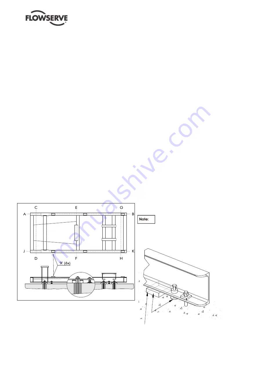
  Level the foundation frame in the direction A-B 

with an accuracy of 0.05 mm/m

1

 using the 

adjusting bolts, see Figure 3. Fill the space 
between the filler blocks and the foundation frame 
with thin filler plates. 

  Tighten the foundation nuts, along the A-B axis, by 

applying a moment equal to ¼ the maximum 
permissible moment (M

max

) of the foundation bolt. 

  Level the foundation frame in the directions C-D, 

E-F and G-H with an accuracy of 0.05 mm/m

1


using the adjusting bolts. Fill the space between 
the filler blocks and the foundation frame with thin 
filler plates. 

  Tighten the other foundation nuts by applying a 

moment equal to ¼ the maximum permissible 
moment (M

max

) of the foundation bolt. 

  Check that the nuts of the foundation bolts are still 

tight. 


  Place the electric motor on the pump center line, 

using shims between the supporting faces of the 
foundation frame and the motor base.The 
maximum allowable deviation in axial or radial 
direction is 0.05 mm and depends on the type of 
coupling.


  Retract all foundation bolts and check that the 

foundation frame is level in all directions with 
an accuracy of 0.05 mm/m

1

  Check the position and level along the center 

line of the suction and discharge nozzles. 
Adjust, if necessary, by following the 
procedures given above. 

  Fill in the outer edges of the foundation frame, 

including filler plates, 

completely,

 using non-

shrinkable mortar (e.g. Pagel V1 or equivalent) 
and let this set in accordance with the 
specifications. 

  Grout the foundation frame, via the fill opening 

(see Figure 3), 

completely,

 using non-

shrinkable concrete and let this set in 
accordance with the specifications. 

  Check that the nuts of the foundation bolts are 

still tight and tighten, if necessary, by applying 
the correct moment (¼ M

max

). 

  If the guard of the mechanical seal was 

removed for levelling, replace it in the correct 
position. 

  If necessary, draw up a report on the whole 

adjustment procedure. 


4.4.1  Baseplate not Intended for Grouting but 
Installed on Concrete Foundations 

 
According to the figure 4.3.1 and 4.4.1 the 
baseplate will not be grouted but only a sealing 
shall be provided. During the preparation, as 
indicated on the General Arrangement drawing a 
certain number of openings into the sealing must 
be guaranteed. After the sealing the blocks used to 
realise the openings must be removed. Blocks has 
to be wider than the baseplate longitudinal beam in 
order to guarantee the opening for the drainage. 

The filler grout must be of a non-

shrinkable kind and fill up the space between the 
beams and the concrete poor. Make sure that filler 
grout is dry before removing the blocks. 
 

Not supplied

BLOCK TO BE REMOVED 

AFTER THE SEALING


Figure 4.3.1 

Figure 3: Adjusting foundation frame 


BLOCK TO BE REMOVED AFTER 
APPLYING THE FILLER GROUT


Summary of Contents for PHL 25.08.05

Page 1: ...gle stage horizontal centrifugal pump PCN 00079593 Ed 10 10 E These instructions should be read prior to installing operating using and maintaining this equipment Компания ПромХимТех официальный дистрибьютор насосов Flowserve www promhimtech ru Тел 8 800 250 01 54 e mail zakaz promhimtech ru ...

Page 2: ...ommended spares and consumable items 21 6 4 Tools required 21 6 5 Fastener torques 22 6 6 Setting impeller clearance 22 6 7 Disassembly 22 6 8 Examination of parts 24 6 9 Assembly 24 7 FAULTS CAUSES AND REMEDIES 27 8 PARTS LIST AND DRAWINGS 29 8 1 Typical Sectional drawing 29 8 2 Typical Parts list 30 8 3 General arrangement drawing 30 9 CERTIFICATION 30 10 OTHER RELEVANT DOCUMENTATION AND MANUALS...

Page 3: ... applicable this document incorporates information relevant to these Directives and Approvals To confirm the applicable Approvals and if the product is CE marked check the serial number plate markings and the Certification See section 9 Certification 1 3 Disclaimer Information in these User Instructions is believed to be reliable In spite of all the efforts of Flowserve Pump Division to provide so...

Page 4: ...n potentially explosive atmospheres section 1 6 4 also applies NEVER DO MAINTENANCE WORK WHEN THE UNIT IS CONNECTED TO POWER GUARDS MUST NOT BE REMOVED WHILE THE PUMP IS IN OPERATION DRAIN THE PUMP AND ISOLATE PIPEWORK BEFORE DISMANTLING THE PUMP The appropriate safety precautions should be taken where the pumped liquids are hazardous FLUORO ELASTOMERS When fitted When a pump has experienced tempe...

Page 5: ...ectrical and non electrical equipment shall meet the requirements of European Directive 94 9 EC 1 6 4 1 Scope of compliance Use equipment only in the zone for which it is appropriate Always check that the driver seal and pump equipment are suitably rated and or certified for the classification of the specific atmosphere in which they are to be installed Where Flowserve has supplied only the bare s...

Page 6: ...ED AND VENTED AND DOES NOT RUN DRY Ensure the pump and relevant suction and discharge pipeline system is totally filled with liquid at all times during the pump operation so that an explosive atmosphere is prevented In addition it is essential to make sure that seal chambers auxiliary shaft seal systems and any heating and cooling systems are properly filled If the operation of the system cannot a...

Page 7: ...rise to sparking or adversely affect the ambient conditions Where there is a risk from such tools or materials maintenance must be conducted in a safe area It is recommended that a maintenance plan and schedule is adopted See section 6 Maintenance 1 7 Nameplate and warning labels 1 7 1 Nameplate For details of nameplate see the Declaration of Conformity 1 7 2 Warning labels ...

Page 8: ...are likely to be encountered They represent sound pressure levels at 1 m 3 3 ft from the directly driven pump for free field over a reflecting plane If a pump unit only has been purchased for fitting with your own driver then the pump only noise levels from the table should be combined with the level for the driver obtained from the supplier If the motor is driven by an inverter it may show an inc...

Page 9: ...pull out unit by the bearing support see Figure 2 Figure 2 2 3 3 Lifting with foundation frame The unit must be lifted at the lifting lugs or eye bolts of the base plate For lifting of the total unit a lifting beam or lifting frame shall be used to avoid damaging of the E motor seal plan interconnecting piping and or instruments Unsafe lifting is never allowed A crane shall be used for all pump se...

Page 10: ...etween the pump casing and seal plate for optimum concentricity The design enables a number of sealing options to be fitted 3 3 6 Shaft seal The mechanical seal s attached to the pump shaft seals the pumped liquid from the environment Gland packing may be fitted as an option for non hazardous service only 3 3 7 Driver The driver can be an electric motor or diesel motor or turbine 3 3 8 Accessories...

Page 11: ...hese recesses in the base in accordance with the above figure referring to the dimensional drawing of the pump unit If a concrete base is used observe the following points do not place the pump unit on the base until it is completely set fill the recesses with water at least 24 hours before grouting the foundation bolts Wetting the recesses will strengthen the bond between the mortar of the founda...

Page 12: ...on is 0 05 mm and depends on the type of coupling Retract all foundation bolts and check that the foundation frame is level in all directions with an accuracy of 0 05 mm m 1 Check the position and level along the center line of the suction and discharge nozzles Adjust if necessary by following the procedures given above Fill in the outer edges of the foundation frame including filler plates comple...

Page 13: ... in one direction may alter the alignment in another direction Always check in all directions after making any adjustment Coupled equipment must be aligned to minimise unnecessary stresses in shafts bearings and coupling Flexible couplings will not compensate for appreciable misalignment Foundation settling thermal expansion or nozzle loads resulting in baseplate foundation deflection and vibratio...

Page 14: ... dial indicator as shown below to check both parallel and angular alignment Parallel Angular Figure 4 8 Maximum permissible misalignment at working temperature Parallel 0 05 mm 0 002 in TIR Angular 0 025 mm 0 001 in TIR Pumps with thick flanged non spacer couplings can be aligned by using a straight edge across the outside diameters of the coupling hubs and measuring the gap between the machined f...

Page 15: ...val of the pump 4 6 2 Suction piping a The inlet pipe should be one or two sizes larger than the pump inlet bore and pipe bends should be of a radius as large as possible b Pipework reducers should have a maximum total angle of divergence of 15 degrees c Keep the total length of the suction pipe as short as possible d A bend in the suction pipe should be located at a distance of at least 5 times t...

Page 16: ...dvice 4 7 4 The motor must be wired up in accordance with the motor manufacturer s instructions normally supplied within the terminal box including any temperature earth leakage current and other protective devices as appropriate The identification nameplate should be checked to ensure the power supply is appropriate 4 7 5 A device to provide emergency stopping must be fitted 4 7 6 If not supplied...

Page 17: ...fingbox cooling is required depending on the sealselection and conditions required to the seal In general this means that stuffingbox cooling is not required when a cooling system on the sealharness is sufficient to maintain a constant duty temperature of the seal which is lower than the design temperature of the seal However because not all factors which have their impact on the temperature and d...

Page 18: ...w for a period after the pump has been stopped Never run a mechanical seal dry not even for a short time 5 9 3 Bearings If the pumps are working in a potentially explosive atmosphere temperature or vibration monitoring is recommended If bearing temperatures are to be monitored it is essential that a benchmark temperature is recorded at the commissioning stage and after the bearing temperature has ...

Page 19: ...ower absorbed increases with increased viscosity and reduces with reduced viscosity It is important that checks are made with your nearest Flowserve office if changes in viscosity are planned 5 11 3 Pump speed Changing pump speed effects flow total head power absorbed NPSHR noise and vibration The flow is directly proportion of the pump speed head varies as speed ratio squared and power varies as ...

Page 20: ...hen using cleaning agents 6 1 Maintenance schedule It is recommended that a maintenance plan and schedule is adopted in line with these User Instructions It should include the following a Any auxiliary systems installed must be monitored if necessary to ensure they function correctly b Gland packings if applied instead of a mechanical seal must be adjusted correctly to give visible leakage and con...

Page 21: ...re shown on the pump nameplate To ensure continued satisfactory operation replacement parts to the original design specification should be obtained from Flowserve Any change to the original design specification modification or use of a non standard part will invalidate the pump s safety certification 6 2 2 Storage of spares Spares should be stored in a clean dry area away from vibration Inspection...

Page 22: ...t the casing cover up Work carefully as there is not much clearance between the diffuser and the pump casing remove the packing ring 4590 2 from the pump casing and dispose of this in the proper way This type of packing may only be used once 6 7 3 Removing the diffuser This procedure describes removal of the diffuser from the casing cover Bend open the lock washers 6541 and remove the hexagon head...

Page 23: ...e a suitable extraction tool must be used for disassembly Remove set screws 6570 2 These set screws lock the impeller wearing ring on the impeller Remove the impeller wearing ring from the impeller using the extraction tool Drill 3 holes at 120 intervals in the partition between impeller wearing ring and impeller Drill the holes to a depth such that the set screws 6570 2 do not protrude above the ...

Page 24: ...ller bearing 3012 and the axial ball bearing 3013 Push the inner ring of the radial roller bearing on the pump shaft Put the spring washer 6545 on the pump shaft for the radial roller bearing Push the axial ball bearing on the pump shaft Push the lock washer 2911 for the axial ball bearing and install the bearing nut 2910 on the pump shaft Lock the bearing nut by bending the lips of the lock washe...

Page 25: ...rtically in the diffuser and wait until the case wearing ring is tight Drill 3 holes at 120 intervals in the partition between the case wearing ring and diffuser Drill the holes to a depth such that the set screws 6570 2 do not protrude above the surface of the case wearing ring and the diffuser plate Tap screw thread into the 3 holes and remove the metal chips Mount the set screws 6570 2 Fix the ...

Page 26: ... paste Place a new packing ring 4590 2 onto the rim of the pump casing Attach lifting devices at the appropriate lifting points Observe the lifting instructions described in section 2 3 Lift the casing cover towards the pump casing and make sure that the casing cover is in the correct position in relation to the pump casing There is only one way for the casing cover to fit onto the pump casing Car...

Page 27: ...parts CONSULT FLOWSERVE Foot valve too small Investigate replacing the foot valve Foot valve partially clogged Clean foot valve Inlet of suction pipe insufficiently submerged Check out system design Speed too low CONSULT FLOWSERVE Speed too high CONSULT FLOWSERVE Total head of system higher than differential head of pump Check system losses Remedy or CONSULT FLOWSERVE Total head of system lower th...

Page 28: ...VE Abrasive solids in liquid pumped Internal misalignment of parts preventing seal ring and seat from mating properly Mechanical seal was run dry Check mechanical seal condition and source of dry running and repair Internal misalignment due to improper repairs causing impeller to rub Check method of assembly possible damage or state of cleanliness during assembly Remedy or CONSULT FLOWSERVE if nec...

Page 29: ...lector 6570 1 3 Screw 2540 2 Deflector 6570 2 Screw 2910 Shaft nut 6570 4 Screw 2911 Shaft nut washer 6572 1 Stud 2913 Impeller screw 6572 2 Stud 3012 Radial roller bearing 6575 Jack screw 3013 Thrust ball bearing 6577 1 Hexagon head bolt 3120 Bearing support stool 6577 2 Hexagon head bolt 3200 Bearing housing 6577 3 Hexagon head bolt 3260 1 Bearing cover 6577 4 Hexagon head bolt 3260 2 Bearing co...

Page 30: ...NUALS 10 1 Supplementary User Instructions Supplementary instructions such as for a driver instrumentation controller seals sealant system etc are provided as separate documents in their original format If further copies of these are required they should be obtained from the supplier for retention with these User Instructions 10 2 Change notes If any changes agreed with Flowserve Pump Division are...

Page 31: ...America and Caribbean Flowserve Corporation Pump 6840 Wynnwood Lane Houston Texas 77008 USA Telephone 1 713 803 4434 Fax 1 713 803 4497 Asia Pacific Flowserve Pte Ltd Pump 200 Pandan Loop 06 03 04 Pantech 21 Singapore 128388 Telephone 65 6775 3003 Fax 65 6779 4607 Your Flowserve factory contacts Flowserve B V P O Box 55 Lansinkesweg 30 7550 AB The Netherlands Tel 31 74 2404000 Fax 31 74 2425696 E ...

Reviews: