background image

Limitorque QX Electronic Actuator  FCD LMENIM3314-01 – 06/18

68

6.6.1 Optional Transformer Removal

c


WARNING:

 Hazardous Voltage! Turn off all power sources to actuator before removing control module 

assembly. Power sources may include main power or control power.

CAUTION:

 Potential to cause electrostatic damage to electronic components. Before handling electronic 

components, ensure that you are discharged of static electricity by briefly touching a grounded metal object.

Step 1

Remove controls cover per section 6-2.

Step 2

Remove control module per section 6-3.

Step 3

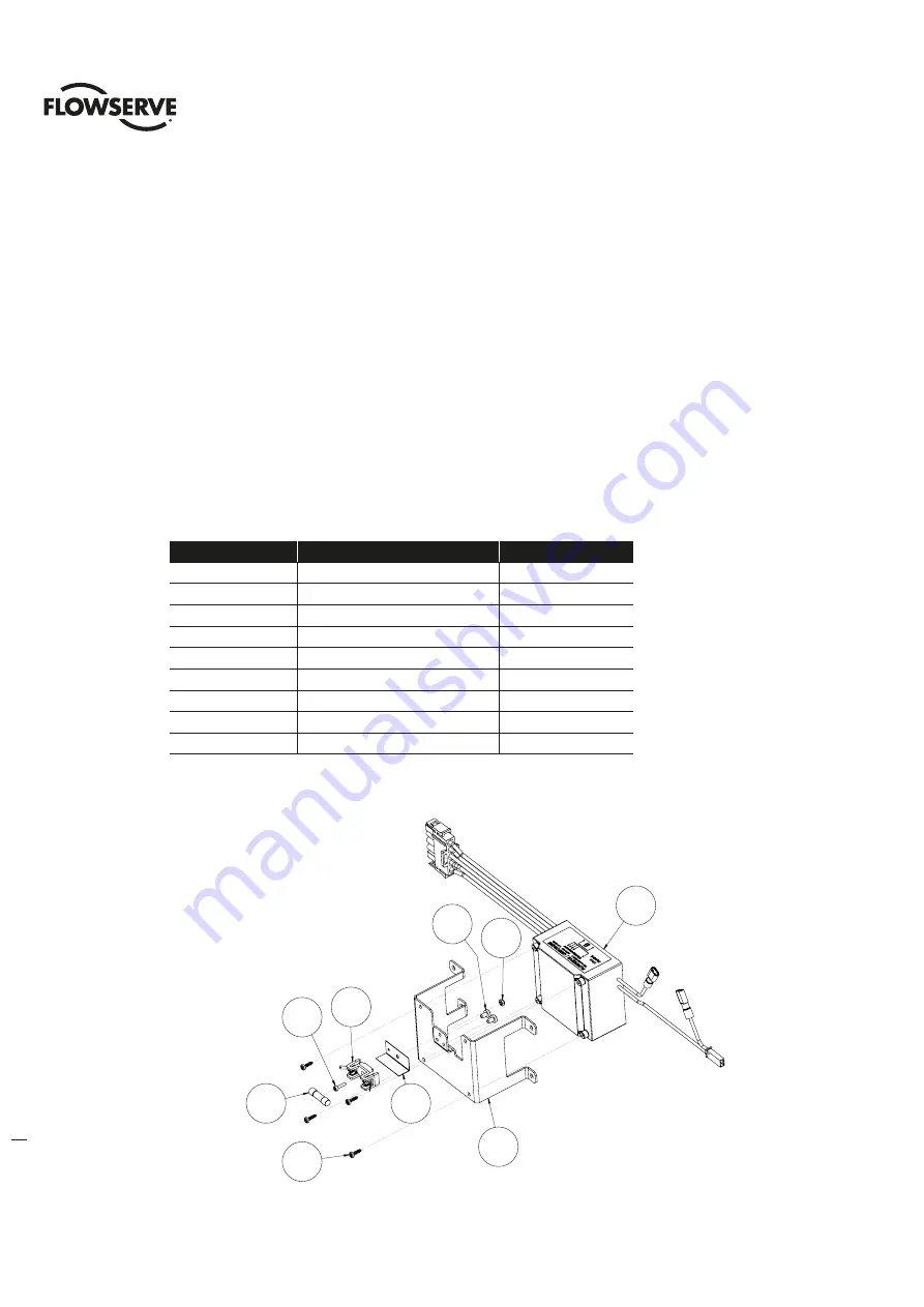
Using a M2.5 hex key, remove the four M3 screws (#2) holding the optional transformer assembly (#1) in place and 
remove from back of control module. If require unplug wiring harness (#3).

Table 6.13 - Optional Transformer Subassembly

ITEM NUMBER

DESCRIPTION

QTY.

1

BRACKET

1

2

OPTIONAL TRANSFORMER

1

3

SOVAL HEAD SCREW

4

4

FUSE BLOCK

1

5

SOCKET HEAD CAP SCREWS

1

6

HEX NUT

1

7

FUSE

1

8

SHIELD, FUSE BLOCK

1

9

SELF TAP SCREW

2

Figure 6.16 Optional Transformer Subassembly

2

1

6

9

8

4

7

3

5

ITEM 9

FUSE BLOCK

ANTI-ROTATION

SCREWS

1

2

6

4

5

7

3

8

9

Item 9

fuse block

anti-rotation

screws

Summary of Contents for Limitorque QX

Page 1: ...Experience In Motion Maintenance and Spare Parts Limitorque QX Electronic Actuator FCD LMENIM3314 01 06 18 ...

Page 2: ... Type A1 A1E Base Thrust QXM only 17 3 2 1 Optional Thrust Base Assembly QX 1 2 17 3 2 2 Optional Thrust Base Assembly Removal 17 3 2 3 Thrust Base Remounting 18 3 2 4 Removal Type A1 A1E Base Actuator Removal Separate from Thrust Base 19 3 2 5 Remounting Type A1 A1E Base Actuator Remounting Separate from Thrust Base19 3 2 6 Removal Type A1 A1E Base Actuator and Thrust Base as a Unit 20 3 2 7 Remo...

Page 3: ...l 54 6 1 2 Terminal Cover Remounting 55 6 2 Controls Cover 55 6 2 1 Controls Cover Removal 56 6 2 2 Controls Cover Subassembly Remounting 57 6 3 Control Modules 58 6 3 1 Control Module Removal 58 6 3 2 Control Module Subassemblies 58 6 3 3 Control Module Remounting 61 6 4 Terminal Block 61 6 4 1 Terminal Block Shield 62 6 4 2 Terminal Block Removal 62 6 5 Mounting of Standard and Optional Controls...

Page 4: ...ntation View 23 Figure 4 4 Handwheel Cover Assembly 24 Figure 4 5 Handwheel Cover Subassembly Item 10 QX 1 2 25 Figure 4 6 Handwheel Cover Subassembly Item 10 QX 3 thru 5 26 Figure 4 7 Handwheel Subassembly Item 10 4 QX 1 2 shown 26 Figure 4 8 Motor Cartridge Assembly Removal 27 Figure 4 9 Motor Cartridge Subassembly Item 5 28 Figure 4 10 Gearing and clutching QX 1 2 29 Figure 4 11 Gearing and clu...

Page 5: ...onal Transformer Subassembly 68 Figure 7 1 Low Voltage QX Unit Wiring Connections 70 Figure 7 2 Low Voltage QX Unit Wiring Connections Version 2 71 Figure 7 3 DC QX Unit Wiring Connections 71 Figure 7 4 High Voltage QX Unit Wiring 72 Figure 7 5 Typical Toroid Transformer Label 72 Figure 7 6 Optional Low Voltage Transformer Harness Wiring 73 Figure 7 7 Optional High Voltage Transformer Harness Wiri...

Page 6: ...3 Optional Thrust Base Assembly 45 Table 4 24 Optional Thrust Base Subassembly 46 Table 5 1 90º Encoder Assembly 48 Table 5 2 Encoder Subassembly Item 14 1 49 Table 5 3 Multi Turn Encoder Assembly 50 Table 5 4 6 5 Turn Spur Gear Subassembly Item 17 2 51 Table 5 5 20 Turn Spur Gear Subassembly Item 17 2 51 Table 6 1 Terminal Cover Assembly 54 Table 6 2 Terminal Cover Subassembly 55 Table 6 3 Contro...

Page 7: ... these instructions when disassembly is required for service maintenance or parts replacement 1 2 Procedure Emphasis Please refer to the following methods used to emphasize text throughout this manual Safety Warnings Cautions and Notes present material that is important to user safety Be sure to read any safety notices you see as they could prevent equipment damage personal injury or even death to...

Page 8: ...tuator and high pressure hazards of the attached valve or other actuated device when installing or performing maintenance on your QX actuator Failure to observe these precautions could result in serious bodily injury damage to the equipment or operational difficulty c WARNING Do not manually operate actuator with devices other than installed handwheel and declutch lever Using additive force device...

Page 9: ...D LMENIM3314 01 06 18 flowserve com 2 QX Actuator Subassembly Figure 2 1 Typical QX Actuator NOTE QX 1 and 2 90 unit shown 11 5 6 7 10 15 3 14 4 14 1 3 10 4 14 8 11 5 6 7 10 15 3 14 4 14 1 3 10 4 14 8 11 14 1 5 6 7 10 10 4 15 3 14 8 3 14 4 ...

Page 10: ...able and advanced protection technology all valve and other actuated devices are protected from potential damage from overload improper seating and foreign obstructions A range of control and network options is available which can be easily added to the control capabilities already available on a standard actuator Contact your local Limitorque distributor or Limitorque sales office for further inf...

Page 11: ...actuator from the shipping carton or skid thoroughly examine it for any physical damage which may have occurred during shipment If you note any damage immediately report the damage to the transport company and call Limitorque for further assistance 2 A nameplate with important information is attached to each actuator Record the following information for use when you need to contact Limitorque with...

Page 12: ...l every 100 hours of operation or if water or other foreign material is found during oil inspection Oil Level Inspection and Fill Criteria To avoid pressurization of the gearcase the following recommended oil capacities should not be exceeded Reference Table 2 3 for oil capacities when mounted in varying positions Actuator viewed in upright position terminal compartment up base down Oil level shou...

Page 13: ...uate subassembly components to determine requirement for a new subassembly If a new subassembly is required see Section 2 5 Once components have been identified and replaced remount following the appropriate Remounting procedures 2 5 How to Order Replacement Subassemblies 2 5 1 Replacement Parts Replacement parts are sold in modular subassemblies therefore when part replacement is required order p...

Page 14: ...he following information to obtain credit for returned goods Return Material Authorization RMA Unit type size Flowserve Limitorque order number Serial number Return parts to the address listed below Limitorque Actuation Systems 5114 Woodall Road Lynchburg VA 24502 2 5 Screw Preload Torque Torque applied to each size screw used in the QX Table 2 4 Screw Preload Torque Screw Screw Preload M10 10 12 ...

Page 15: ...al Type B4 B4E Base Step 1 c WARNING Hazardous Voltage Turn off all power sources to actuator before removing actuator from mounting plate Power sources may include main power or control power If necessary disconnect incoming power leads L1 L2 L3 and control wiring from the terminal block Figure 3 1 Torque Nut F FA 10 QX 1 2 and F FA 12 and 14 QX 1 thru 5 13 7 13 6 13 6 13 7 ...

Page 16: ...ator removal along with optional B4 base Step 2 c WARNING Potential high pressure vessel Before disassembling your actuator ensure that the valve or other actuated device is isolated and is not under pressure Lift the actuator from mounting adapter 3 1 2 Remounting Type B4 B4E Base Step 3 Ensure stem nut 1 22 is secured inside actuator drive sleeve with retaining ring 1 23 Lower the actuator onto ...

Page 17: ...T BASE ASSEMBLY 1 Figure 3 3 Optional Thrust Base Assembly 3 2 2 Optional thrust base assembly removal Step 1 Remove the four 4 screws and remove the thrust base subassembly 16 17 by sliding the base down If base is ISO remove the spacer pilot 16 16 Step 2 Remove the four 4 screws 16 15 and remove the adapter plate 16 14 and torque nut 16 10 Item 16 11 bushing is pressed into adapter plate and can...

Page 18: ...gning nut lugs to drive sleeve slots Step 2 Lightly lubricate O rings 16 12 and 16 13 and insert into bushing 16 11 that is pressed into adapter plate 16 14 Slide adapter plate and bushing over end of torque nut and aligning to unit baseplate Insert screws 16 15 into adapter plate holes and tighten Step 3 Align thrust base subassembly nut lugs 10 3 with QX torque nut 16 10 slots and slide thrust b...

Page 19: ...ntial for actuated device to change position The thrust base will maintain position only if non backdriving thread lead is used Ensure proper thread lead is used in your application before allowing thrust base to be used for main taining position when actuator is removed Thrust base removal if required The valve position will be maintained if a locking thread lead is used on the valve stem If thru...

Page 20: ...RNING Potential high pressure vessel Before disassembling your actuator ensure that the valve or other actuated device is isolated and is not under pressure Declutch the actuator to manual mode STEP 3 Rotate the handwheel until the actuator lifts off the threaded stem 3 2 7 Remounting Type A1 A1E Base Actuator and Thrust Base as a Unit STEP 4 Actuator and thrust base remounting Declutch the actuat...

Page 21: ...when replacing motor Consult your Limitorque representative or the Limitorque factory to replace with correct motor Table 4 1 Motor Parts List ITEM NUMBER DESCRIPTION QTY 11 MOTOR 1 13 4 SOCKET HEAD CAP SCREWS 5 15 1 O RING 1 15 2 COVER MOTOR 1 15 6 SOCKET HEAD CAP SCREWS 3 Figure 4 1 Motor Cover and Motor Subassembly Removal 15 6 15 2 13 4 11 15 1 13 4 15 1 11 15 2 15 6 ...

Page 22: ...ection 6 2 for controls cover removal Section 7 1 for motor connector placement Step 2 a CAUTION The rotor is not connected to the motor housing when removing the motor ensure the rotor is carefully removed and not dropped from the motor housing Using a M3 hex key remove the five M4 screws 13 4 that mount the motor assembly Remove the motor assembly 11 from unit by sliding motor out of the unit an...

Page 23: ...igning the motor coupling bore and slot to the motor cartridge shaft and pin and the motor bracket to the unit housing See Figure 4 3 listed for motor bracket orientation to unit housing Figure 4 3 Motor Bracket Orientation View Step 2 Reconnect motor wiring connector to motor control board Install the five M4 screws 13 4 and tighten See section 7 for motor wiring connection Step 3 Lightly lubrica...

Page 24: ...r declutch lever may cause serious personal injury and or damage to the actuator and valve 4 2 1 Handwheel cover subassembly Removal QX 1 thru 5 Step 1 c WARNING Potential to operate while dangerous mechanical parts are exposed during subassembly removal To prevent injury turn off all power sources to actuator before removing top mounted handwheel assembly Power sources may include main power or c...

Page 25: ...RING 1 10 3 SHAFT HANDWHEEL 1 10 4 HANDWHEEL SUBASSEMBLY 1 10 5 RETAINING RING 1 Figure 4 5 Handwheel Cover Subassembly Item 10 QX 1 2 Table 4 5 Handwheel Cover Subassembly Item 10 QX 3 thru 5 ITEM NUMBER DESCRIPTION QTY 10 1 COVER HANDWHEEL 1 10 2 O RING 1 10 3 SHAFT HANDWHEEL 1 10 4 HANDWHEEL SUBASSEMBLY 1 10 5 WASHER 2 10 6 HEX NUT 1 10 1 10 2 10 3 10 5 10 4 10 2 10 3 10 1 10 4 10 5 ...

Page 26: ... Handwheel Subassembly Item 10 4 ITEM NUMBER DESCRIPTION QTY 1 HANDWHEEL 1 2 SPINNER 1 3 SPINNER ROD 1 4 FLAT WASHER 1 5 SOCKET HEAD CAP SCREW 1 6 HEX NUT 1 7 HANDWHEEL LABEL 1 Figure 4 7 Handwheel Subassembly Item 10 4 QX 1 2 shown 10 1 10 2 10 3 10 5 10 4 10 5 10 6 1 6 2 4 3 5 7 5 10 5 10 3 10 2 10 1 10 4 10 5 10 6 2 3 6 1 7 4 ...

Page 27: ...and the idle shaft assembly see Figure 4 10 for view of idle shaft assembly location Step 2 Fit the 3 screws 13 3 into handwheel cover mounting holes and tighten Check to make sure handwheel rotates freely 4 3 Motor Cartridge Subassembly QX 1 thru 5 NOTE Sections 4 2 4 8 require the actuator to be removed from the mounting plate and the oil drained 4 3 1 Motor Cartridge Subassembly Removal QX 1 th...

Page 28: ...r Cartridge Assembly Remounting Step 1 Lightly lubricate O ring 5 8 Push cartridge subassembly into housing bore assuring motor pinion 5 6 aligns with motor gear on handwheel side of housing Cartridge face should be even or below the counter bore face in the unit housing Place bracket 9 1 and screw 9 2 in countered bored area with M4 tap and tighten screw Note The bracket must sit flat on cartridg...

Page 29: ...SUBASSEMBLY 1 7 CLUTCH FORK SUBASSEMBLY 1 9 4 PLATE GEAR 1 9 5 SOCKET HEAD FLAT SCREW 2 9 6 BRACKET DECLUTCH 1 9 7 SOCKET HEAD FLAT SCREW 2 9 8 O RING 1 9 9 DECLUTCH LEVER 1 9 10 SOCKET HEAD CAP SCREW 1 9 11 EXTENSION SPRING 1 9 12 BRACKET 1 9 13 BALL BEARING 1 9 14 SOCKET HEAD CAP SCREW 1 9 15 SPACER DECLUTCH SPRING 1 Figure 4 10 Gearing and clutching QX 1 2 9 9 9 8 9 7 9 6 9 4 9 5 6 9 13 9 14 7 ...

Page 30: ...KET HEAD FLAT SCREW 2 9 6 BRACKET DECLUTCH 1 9 7 SOCKET HEAD FLAT SCREW 2 9 8 O RING 1 9 9 DECLUTCH LEVER 1 9 10 SOCKET HEAD CAP SCREW 1 9 11 EXTENSION SPRING 1 9 12 BRACKET 1 9 13 BALL BEARING 1 9 14 SOCKET HEAD CAP SCREW 1 9 15 SPACER DECLUTCH SPRING 1 Figure 4 11 Gearing and clutching QX 3 thru 5 9 9 9 8 9 7 9 6 8 9 4 9 5 6 9 12 9 2 9 14 9 10 7 9 13 9 3 9 3 9 11 9 15 9 2 9 12 6 9 3 8 9 3 9 4 9 ...

Page 31: ...k and clutch shaft subassembly Using a M2 5 hex key remove M3 screw 9 10 holding clutch fork 7 subassembly and declutch lever 9 9 in place Remove declutch lever 9 9 and O ring 9 8 by sliding lever up and out of housing Gently pull out the clutch shaft subassembly 6 and clutch fork subassembly 7 out of unit thru the handwheel cover bore Step 3 Spur idler subassembly QX 3 4 5 only Gently pull out sp...

Page 32: ...y Item 6 QX 3 Thru 5 ITEM NUMBER DESCRIPTION QTY 6 1 CLUTCH SHAFT 1 6 2 MOTOR CLUTCH GEAR 1 6 5 CLUTCH 1 6 6 COMPRESSION SPRING 1 6 7 WASHER 2 6 8 RETAINING RING 2 Figure 4 13 Clutch Shaft Subassembly Item 6 QX 3 thru 5 6 1 6 2 6 3 6 4 6 5 6 6 6 7 6 8 6 1 6 2 6 7 6 8 6 5 6 6 6 7 6 8 6 4 6 2 6 5 6 3 6 1 6 6 6 7 6 8 6 2 6 1 6 8 6 6 6 8 6 7 6 5 6 7 ...

Page 33: ...hole with the ball bearing 2 8 bore Note that the two counter sunk holes is for the two flat head screws 9 5 Fit the two M4 flat head screws 9 5 and tighten with a M2 5 hex key Step 3 Spur idler subassembly QX 3 Thru 5 only Place ball bearing 9 3 in housing bore the bore without the bearing plate Slide in the spur idler subassembly 8 into bearing 9 3 with the big gear end of the idler shaft first ...

Page 34: ...on to M3 screw and secure assembly to bottom tap in declutch lever The spacer should be in between the spring and declutch lever Place M4 screw 9 2 into spring bracket 9 12 Hook the spring bracket on to the declutch return spring 9 14 that has already been installed on to the lever See Figure 4 16 for correct hole for spring to hook into Carefully stretch the spring and position the M4 screw in pl...

Page 35: ...Figure 4 17 Pipe Plug NOTE If the pipe plug was removed pipe sealant or tape must be applied to plug threads before remounting 4 6 Baseplate 4 6 1 Baseplate Removal NOTE Sections 4 2 4 8 require the actuator to be removed from the mounting plate and the oil drained NOTE If unit has a F FA 05 or 07 QX 1 2 F FA 10 QX 3 thru 5 base or Thrust base attached these bases must be removed before removing t...

Page 36: ... SCREWS 4 Figure 4 18 Baseplate F FA 10 QX 1 2 F FA 12 14 QX 3 thru 5 Step 1 Using a M8 hex key remove the M10 screws 4 2 and remove baseplate 3 Table 4 16 Baseplate subassembly Item 3 ITEM NUMBER DESCRIPTION QTY 3 1 BASEPLATE 1 3 2 QUAD RING 1 3 3 BUSHING 1 Figure 4 19 F FA 10 QX 1 2 F FA 12 14 QX 3 thru 5 Baseplate Subassembly Item 3 QX 1 2 Baseplate shown 4 1 3 4 2 3 1 3 2 3 3 4 1 4 2 3 3 1 3 2...

Page 37: ...l always be the same with the 4 mounting taps straddling centerline 2 QX 3 thru 5 baseplate mounts with 8 screws and orientation depends on add on base options A If not adding on any base options the 4 mounting taps in base should be straddling centerline B If adding smaller F FA 10 base the 4 mount taps should be on centerline 4 7 Worm Shaft Assembly NOTE Sections 4 2 4 8 require the actuator to ...

Page 38: ... 1 8 that is in back of the worm shaft NOTE The drive sleeve will rotate when knocking out worm shaft Be sure that the drive sleeve is off of stops or damage to drive sleeve stops and or housing could accrue Step 3 If replacing bearings but not worm shaft remove round retaining ring 2 5 to remove thrust bearing 2 3 and needle bearing 2 2 from worm shaft If replacing worm shaft thrust bearing and n...

Page 39: ...te needle bearing 2 2 and place in housing and around worm shaft Using special tools from Flowserve lightly press needle bearing into housing until tool bottoms out Needle bearing should be even with housing counter bore Check that the worm shaft rotates freely and has freedom to be moved in and out Step 4 Special tools required contact factory for ordering information Lubricate thrust bearing 2 3...

Page 40: ... NUMBER DESCRIPTION QTY 1 1 HOUSHING 1 1 2 BUSHING 1 1 3 OIL SEAL 1 1 5 BALL BEARING SEALED 2 1 6 SHAFT ENCODER 1 1 7 RETAINING RING 1 1 8 DISC 1 1 9 NEEDLE BEARING 1 1 10 INSERT 1 1 11 DRIVE SLEEVE 1 1 12 STOPS 2 1 13 O RING 2 1 14 SOCKET HEAD CAP SCREW 2 Figure 4 21 Drive Sleeve Stops and Encoder Shaft Assembly 1 2 1 5 1 3 1 7 1 10 1 11 1 14 1 12 1 13 1 5 1 6 1 1 1 8 1 9 90 UNIT STOPS SHOWN 1 5 ...

Page 41: ... driver down the center of the insert and prying out the insert Step 2 Stop removal Loosing screws 1 14 using a M3 hex key Using a flat head screw driver rotate the mechanical stops CCW to remove Step 3 Encoder shaft removal NOTE The encoder must be removed before this step See Section 5 Encoder Assemblies Using retaining ring pliers remove retaining ring 1 7 Grab the encoder shaft 1 6 from the te...

Page 42: ...flat washer 1 8 in bottom of housing worm shaft bore making sure the washer is flat in bottom of housing bore Note that this washer is needed if worm shaft is to be removed at any time in the future Lubricate needle bearing 1 9 and using special tools from Flowserve lightly press or hammer needle bearing into housing until seated Step 4 Mechanical Stop assembly If needed replace O ring 1 13 on sto...

Page 43: ... screws 4 2 and remove baseplate 3 QX 1 2 ISO F 05 or 07 baseplate Using a M8 hex key For ISO baseplate remove the M10 screws 4 2 and remove baseplate 3 QX 3 4 5 MSS FA 10 baseplate Using a 1 2 hex key For MSS baseplate remove the 5 8 11 screws 4 2 and remove baseplate 3 QX 3 4 5 ISO F 10 baseplate Using a M14 hex key For ISO baseplate remove the M16 screws 4 2 and remove baseplate 3 4 9 2 Optiona...

Page 44: ... QTY 13 6 TORQUE NUT 1 13 7 SCO HEAD CAP SCREW 1 Figure 4 25 Torque nut F FA 10 QX 1 2 and F FA 12 and 14 QX 1 thru 5 Table 4 22 Torque nut F FA 05 and 07 QX 1 2 and F FA 10 QX 1 thru 5 ITEM NUMBER DESCRIPTION QTY 13 7 SOCKET HEAD CAP SCREW 1 16 7 TORQUE NUT 1 Figure 4 26 Torque nut F FA 05 and 07 QX 1 2 and F FA 10 QX 1 thru 5 13 7 13 6 13 6 13 7 13 7 16 1 16 1 13 7 ...

Page 45: ...d 1 of 8 positions every 45 on the QX 3 thru 5 Make sure the torque nut is in the position needed Slide torque into drive sleeve aligning pilot and lugs Place screws in torque nut holes and tighten Remount baseplate 4 11 Optional Thrust Base Assembly QX 1 2 Table 4 23 Optional Thrust Base Assembly ITEM NUMBER DESCRIPTION QTY 16 10 TORQUE NUT 1 16 11 BUSHING 1 16 12 O RING 1 16 13 O RING 1 16 14 AD...

Page 46: ...s held in place by the unit drive sleeve and the bushing 16 11 Table 4 24 Optional Thrust Base Subassembly ITEM NUMBER DESCRIPTION QTY 10 1 HOUSING THRUST BASE 1 10 2 PILOT THRUST BASE 1 10 3 THRUST NUT 1 10 6 SOCKET HEAD CAP SCREWS 1 10 7 FLAT WASHER 1 10 8 RELIEF FITTING 1 10 10 SOCKET HEAD CAP SCREWS 4 10 11 GREASE FITTING 1 10 12 NEEDLE BEARING 2 10 13 THRUST RACE 2 10 14 QUAD RING 1 10 15 O R...

Page 47: ...6 11 that is pressed into adapter plate 16 14 Slide adapter plate and bushing over end of torque nut and aligning to unit baseplate Insert screws 16 15 into adapter plate holes and tighten Step 3 Align thrust base subassembly nut lugs 10 3 with QX torque nut 16 10 slots and slide thrust base on to QX unit baseplate aligning pilots Note For ISO thrust base pilot spacer 16 16 must be used to align t...

Page 48: ... 1 NOTE The terminal block must be removed before removing the encoder See section 6 4 for terminal block removal Disconnect the encoder ribbon cable connector from the Motor controller board See Section 7 1 for connector placement Using M3 Hex key remove the three screws 14 2 that mount the encoder Gently pull the encoder up and out of the housing thru the terminal block bore 14 2 14 1 ALIGN ENCO...

Page 49: ... Unit Assembly View NOTE The encoder rotor can only be mated to the encoder shaft in one position The encoder shaft has 3 flats that must align correctly to the encoder rotor ID and ribs Figure 5 3 Encoder To Unit Assembly View Step 2 Install the three M4 screws thru encoder and standoff assembly 14 2 and tighten Take note not to over tighten Step 3 Reconnect encoder ribbon cable to motor controll...

Page 50: ...t be removed before removing the encoder See section 6 4 for terminal block and controls removal Disconnect the encoder ribbon cable connector from the Motor controller board See section 6 for connector placement Using M3 Hex key remove the three screws 17 6 that mount the encoder Gently pull the encoder up and out of the housing thru the terminal block bore Step 2 Using M3 Hex key QX 1 2 or M2 5 ...

Page 51: ...assembly up and over encoder shaft and pinion and out the controls area bore in housing QX 1 and 2 remove the two spacers 17 4 not used in QX 3 thru 5 The dowel pin 17 1 is press into the housing Table 5 4 6 5 Turn Spur Gear Subassembly I tem 17 2 ITEM NUMBER DESCRIPTION QTY 1 TOP PLATE 1 2 SHAFT ENCODER 1 3 GEAR 1 4 ROLL PIN 1 5 BOTTOM PLATE 1 6 STANDOFF 3 7 COMBO HEAD SCREW 6 Figure 5 5 6 5 Turn...

Page 52: ...on view Insert the two screws 17 3 and tighten Firgure 5 7 20 Turn Gear Slot Orientation View Step 2 Place spacers 17 4 QX 1 2 only in place in between the spur assembly bottom plate and the housing lower pads Note that this step can be done before step 1 Insert screws 17 5 and tighten Step 3 Slide the encoder assembly into housing and down over encoder shaft 2 on multi turn spur assembly aligning...

Page 53: ...e encoder shaft has 3 flats that must align correctly to the encoder rotor ID and ribs See Figure 5 3 for reference Step 4 Install the three M4 screws thru encoder and standoff assembly 17 6 and tighten Take note not to over tighten Step 5 Reconnect encoder ribbon cable to motor controller board See section 6 for connector position on motor control board ...

Page 54: ...G Hazardous Voltage Turn off all power sources to actuator before removing control module assembly Power sources may include main power or control power a CAUTION Potential to cause electrostatic damage to electronic components Before handling electronic components ensure that you are discharged of static electricity by briefly touching a grounded metal object Step 1 Using a M6 hex key remove the ...

Page 55: ...erminal Cover Remounting Step 1 Lightly lubricate O ring 8 13 and install around terminal cover spigot pilot 8 12 Slide terminal cover spigot pilot into the unit housing Step 2 Fit the 4 screws 15 6 into terminal cover subassembly mounting holes and tighten to torque in section 2 6 2 Controls Cover Table 6 3 Controls Cover Assembly ITEM NUMBER DESCRIPTION QTY 15 3 CONTROLS COVER SUBASSEMBLY 1 15 6...

Page 56: ...er take care not to pull on cables that connect to the controls cover main board Table 6 4 Controls Cover Subassembly ITEM NUMBER DESCRIPTION QTY 1 49 SHIELD MAIN BOARD 1 7 2 O RING 1 7 3 BLACK KNOB 1 7 4 RED KNOB 1 7 6 SELF TAPPING SCREW 2 7 7 BLACK KNOB CAP 1 7 12 TORSION SPRING 1 7 14 RED KNOB CAP 1 7 17 CONTROLS COVER 1 7 18 WINDOW 1 7 19 O RING RETAINER 1 7 20 RETAINING RING 1 7 21 O RING 1 7...

Page 57: ...pigot pilot into the unit housing insuring not to pinch wiring Step 2 Fit the 4 screws 15 6 into controls cover mounting holes and tighten to torque in section 2 6 3 Control Modules Table 6 5 Control Module Assembly ITEM NUMBER DESCRIPTION QTY 14 8 CONTROLS SUBASSEMBLY 1 14 9 SOCKET HEAD CAP SCREWS 3 14 11 BRACKET CONNECTOR RETAINER 1 14 12 SOCKET HEAD CAP SCREWS 1 7 7 7 14 7 6 7 6 7 3 7 4 7 12 1 ...

Page 58: ...y Slightly rotate the complete control module subassembly in a counterclockwise CCW direction until the keyholes slots in the control module chassis plate 1 1 allow the head of the screws to pass thru and remove controls subassembly 6 3 2 Control Module Subassemblies Table 6 6 Low Voltage Less than 250 VAC Control Module Subassembly ITEM NUMBER DESCRIPTION QTY 1 1 CHASSIS PLATE 1 1 2 MOTOR CONTROL...

Page 59: ... TOROID 2 3 TRANSFORMER TOROID 1 4 MOUNTING PLATE TOROID 1 5 FLAT WASHER 2 6 HEX HEAD CAP SCREW 1 7 HEX NUT 1 8 MOTOR CONTROLLER BOARD 1 13 SPACER 4 14 SHIELD 1 15 PAN HEAD CAP SCREW 4 16 COVER IRAM 1 17 RIBBON CABLE 1 Figure 6 7 High Voltage Greater than 250 VAC Control Module Subassembly 1 18 1 1 1 7 1 2 1 10 1 9 1 1 8 1 16 1 14 1 11 1 12 1 11 1 17 1 13 1 15 1 7 1 2 1 10 1 9 1 14 1 10 1 18 1 9 1...

Page 60: ...D 1 6 SOCKET HD CAP SCREWS 1 7 BRACKET CONNECTOR RETAINER OPTIONAL 1 8 WIRING HARNESS 1 Figure 6 8 DCV Control Module Subassembly NOTE If optional bracket Item 7 is not used the flat washer Item 1 and short standoff Item 2 will be replaced with the long spacer Item 3 3 2 6 5 1 MOTOR CONTROLLER BOARD ASSEMBLY PER FIGURE 6 3 2 4 7 OPTIONAL 8 1 2 3 4 5 6 Motor controller board assembly per figure 6 3...

Page 61: ... the long tang sits in between the Iram heat sink cover 1 9 or 16 and connector on control module For AC controls Insert screw 14 12 in to retainer hole 14 11 and tighten For DC controls Insert flat washer 1 and standoff 2 in to retainer hole 14 11 and tighten See Figure 6 9 Figure 6 9 Bracket Connector Retainer Assembly 6 4 Terminal Block Table 6 9 Terminal Block Assembly ITEM NUMBER DESCRIPTION ...

Page 62: ...al block cover 6 5 Mounting of Standard and Optional Controls 6 5 1 Installation NOTE RESTRICTIONS ON OPTION BOARD COMBINATIONS Only one of the following can be on any unit Modbus DDC Profibus PA Profibus DP FOUNDATION Fieldbus DeviceNet 14 5 14 4 14 3 M3 X 5 SELF LOCK SCREW USE QTY OF TWO 2 TO MOUNT SHIELD USE 2 SCREWS FROM TERMINAL BLOCK OR FROM END USERS BAG SHIELD TERMINAL BLOCK 14 5 14 3 14 4...

Page 63: ...nnect Cable J1 12 pin to socket J5 12 pin on the main board Connect cable J5 22 pin to socket J3 on DigOut board STEP 4 Option OC 8 5A R contacts and 1 5A MR monitor relay 2 Digital Output boards connection Connect to the control cover using four 4 M4x40 pan head screws Ensure that the jumper on DigOut board 1 is in the 1 2 position and the jumper on DigOut board 2 is in the 3 4 position Connect t...

Page 64: ...rminal block to socket J8 Set aside yellow ground wire to be fastened to top of option board stack per Figure 6 14 Above the shield the wire must make contact with the screw STEP 11 QX Quik auxiliary power board a CAUTION Use proper tools and only apply light pressure when installing standoffs to avoid damage to circuit board Installation without option boards 1 Move JP1 jumper to the NORM positio...

Page 65: ... for unit to shut off 7 Carefully remove electronics and Quik Board 8 Locate JP1 jumper on JP1 of Quik Board and move to FAST DISCHARGE PINS PLACE STANDOFFS IN HOLES MARKED A RIBBON CABLE INCLUDED W BOARD COMPONENTS 4X STANDOFF MOUNTED THIS SIDE AS SHOWN QUIK POWER BOARD MUST BE MOUNTED AT END OF BOARD STACK CONTROLS COVER ASSEMBLY CONNECT RIBBON CABLE TO J2 ON MAIN BOARD WHEN USED WITH OPTION BOA...

Page 66: ...L OUTPUT BOARD BETWEEN ONE OPTION BOARD AND THE MAIN BOARD OR BETWEEN 2 OPTION BOARDS BEND UP TAB 2 PLACES OPTION BOARD 3 OPTION BOARD 4 TOP SHIELD REQUIRED IF ONE OR MORE OPTION BOARDS ARE PROVIDED OPTION BOARD 2 OPTION BOARD 1 MOUNTING SCREWS SEE TABLE FOR PART NUMBER AND SIZE CONTROLS COVER ASSEMBLY GROUND WIRE FOR DEVICENET BOARD MUST BE MOUNTED UNDER TOP OPTION BOARD ABOVE THE SHIELD AND CONT...

Page 67: ...to position wires so that they pass perpendicularly over the housing flange NOTE The face of the ACP may be installed in any one of four 90 incremental positions When changing ACP position avoid over twisting the ribbon cable s Rotate the ACP until the display orientation of the front face is correct for normal viewing and then slide the ACP assembly into the actuator housing 6 5 2 Removal For rem...

Page 68: ...t Step 1 Remove controls cover per section 6 2 Step 2 Remove control module per section 6 3 Step 3 Using a M2 5 hex key remove the four M3 screws 2 holding the optional transformer assembly 1 in place and remove from back of control module If require unplug wiring harness 3 Table 6 13 Optional Transformer Subassembly ITEM NUMBER DESCRIPTION QTY 1 BRACKET 1 2 OPTIONAL TRANSFORMER 1 3 SOVAL HEAD SCR...

Page 69: ... control module chassis plate see Figure 6 16 for orientation Fit the four M3 screws 2 thru bracket holes aligning with the taps in on the control module and using a M2 5 hex key tighten the four M3 screws Step 2 Connect wiring See section 7 for wiring connections Note that the optional transformer wiring harness 3 must have the correct wire to connector position per voltage supply See Table 7 1 ...

Page 70: ...RD BOARD 12 PIN HEADER J5 TERMINAL BLOCK 18 PIN CONNECTOR J2 TO MAIN BOARD BOARD 18 PIN HEADER J8 ENCODER RIBBON CABLE 10 PIN CONNECTOR TO MOTOR CONTROL BOARD 10 PIN HEADER J9 MOTOR HARNESS 2 PIN CONNECTOR TO MOTOR CONTROL BOARD 14 PIN HEADER J3 MAIN BOARD LOW VOLTAGE MODULE ASSEMBLY WITH MOTOR CONTROLLER BOARD 68 825 0007 4 Terminal block 3 pin connector J9 to motor control board 3 pin connector ...

Page 71: ...825 0012 TERMINAL BLOCK 3 PIN CONNECTOR J9 TO DC BOARD 3 PIN CONNECTOR WIRING HARNESS ITEM 8 2 PIN CONNECTOR TO DC BOARD 2 PIN CONNECTOR WIRING HARNESS ITEM 8 3 PIN CONNECTOR MOTOR CONTROL BOARD 3 PIN CONNECTOR TERMINAL BLOCK 3 PIN CONNECTOR J9 TO MOTOR CONTROL BOARD 3 PIN CONNECTOR J2 MOTOR HARNESS 14 PIN CONNECTOR TO MOTOR CONTROL BOARD 14 PIN HEADER J2 ENCODER RIBBON CABLE 10 PIN CONNECTOR TO M...

Page 72: ...dule and optional transformer See below for wiring configurations All other wiring is the same as the low or high voltage connections NOTE See Figure 7 9 for wiring harness configurations per supply input voltage TERMINAL BLOCK 3 PIN CONNECTOR J9 TO TOROID TRANSFORMER BLACK BLACK WIRES 3 PIN CONNECTOR HIGH VOLTAGE MODULE ASSEMBLY TORIOD TRANSFORMER BLUE BLUE WIRES 3 PIN CONNECTOR TO J2 3 PIN CONNE...

Page 73: ...L BLOCK HARNESS CONNECTOR J9 SEE FIGURE FOR CORRECT WIRE TO CONNECTOR POSITION FOR SUPPLY INPUT VOLTAGE 3 PIN CONNECTOR FROM TOROID TRANSFORMER TO MOTOR CONTROLLER BOARD 3 PIN CONNECTOR FROM WIRING HARNESS TO TERMINAL BLOCK 3 PIN CONNECTOR FROM WIRING HARNESS WITH LONG WIRES TO TOROID TRANSFORMER ROUTE WIRES AS SHOWN AROUND TRANSFORMER AND INSIDE OF THE SPACERS TO FLAT SIDE OF CHASSIS PLATE 5 PIN ...

Page 74: ...187 209vac 391 420vac N A PIN NUMBER 5 N A 421 495vac 561 600vac 7 4 Terminal Block Wiring Harness Numbers Figure 7 10 Terminal Block Wiring Harness And Connector Numbers 5 4 3 2 1 SEE TABLE FOR WIRE AND SOCKET PIN LOCATION IN 5 PIN CONNECTOR PIN NUMBER 1 3 PIN CONNECTOR J9 12 PIN CONNECTOR J1 3 PIN CONNECTOR J8 18 PIN CONNECTOR J2 4 PIN CONNECTOR J4 22 PIN CONNECTOR J5 2 PIN CONNECTOR J6 4 PIN CO...

Page 75: ...ach in order to support the product for life 1 Stem nut 2 Worm shaft subassembly 3 Drive sleeve subassembly 8 1 2 Bearings O rings and Seals All bearings should be replaced any time an actuator is refurbished Therefore all bearings should be planned for stock for any scheduled refurbishment In addition any O ring or seals should be replaced any time an actuator is disassembled Complete actuator se...

Page 76: ... rings at the top and bottom of the drive sleeve Drive sleeve assembly which includes the worm gear Wormshaft assembly Encoder cartridge assembly Motor assembly Fuse Controls quantity 1 Fuses Power quantity 2 Encoder assembly Motor controller board Control module includes PCB power main CP and optional DDC and I O boards Bronze stem nut for thrust base multi turn QXs only NOTE Oil should be change...

Page 77: ... 2 Frequency of operation 3 Modulating duty 4 Frequent operation by handwheel 5 Regular testing 8 Stall overload condition Flowserve strongly recommends using OEM parts to support and maintain your QX actuator Installing parts other than genuine Flowserve Limitorque parts could cause premature failure of your actuator and voids any remaining warranty The above guidelines are provided to assist you...

Page 78: ... 50082 1 2 IEC 801 3 IEC 801 6 ESD IEC 801 2 EFT Bursts IEC 801 4 Surge Immunity IEC 801 5 ANSI IEEE C62 41 Mains power Harmonics MIL STD 462 Method CSO1 CSO2 Airborne Noise MIL STD 740 1 Table 1 and EN 60204 ATEX Harmonized Standards prEN 60079 0 200X IEC 60079 0 2007 EN 60079 1 2007 EN 60079 7 2007 EN 60529 1991 A1 2000 EN 13463 1 2009 EN 13463 5 2003 Materials of Construction Terminal Control C...

Page 79: ...C6100 4 5 2001 AC Power _2kV com _1kV diff Signal leads _0 5kV com _1kV diff Perf criterion B Conducted RF immunity IEC6100 4 6 1996 150kHz to 80MHz 10Vrms Perf criterion A w 80 AM modulation 1KHz Magnetic field immunity IEC6100 4 8 1993 Power line frequency 30A m 60Hz Perf criterion A Voltage dips and interrupts IEC6326 1 2005 IEC61000 4 11 2004 60Hz 100 dip 1 cycle duration 40 dip 10 cycle durat...

Page 80: ...ectric valve actuators shall conform to the following requirements The X suffix to the Certificate number relates to the following specific conditions of use 1 ISO Class 12 9 M8 socket head cap screws Yield Stress 1100 MPa shall be used to replace the terminal control or motor compartment fasteners of actuators marked with TAMB 20 C or for all Group IIC actuators 2 Stainless steel A2 or A4 ISO Cla...

Page 81: ...e surface temperature of accessible parts or radiation which cause a danger are not produced c Eliminate non electric dangers which are revealed by experience d Assure that foreseeable conditions of overload shall not give rise to dangerous situations And where these risks are wholly or partly covered by other Community Directives the equipment satisfies the requirements of those specific Directiv...

Page 82: ... intended function safely during its useful life However the purchaser or user of Flowserve products should be aware that Flowserve products might be used in numerous applications under a wide variety of industrial service conditions Although Flowserve can and often does provide general guidelines it cannot provide specific data and warnings for all possible applications The purchaser user must th...

Reviews: