Installation
Instructions
Experience In Motion
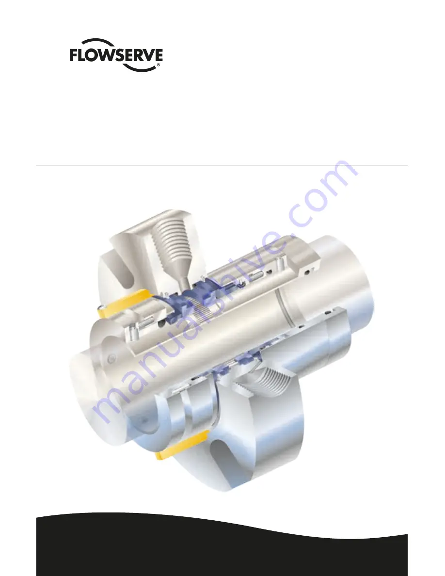
Cartridge dual pusher seal for standard and big bore ANSI pumps
Durametallic
®
P-200
Page 1: ...Installation Instructions Experience In Motion Cartridge dual pusher seal for standard and big bore ANSI pumps Durametallic P 200...
Page 2: ...sure in the system Consult plant MSDS files for hazardous material regulations Seal Chamber Requirements Figure 1 To first obstruction Shaft or sleeve OD 0 000 mm 0 000 inch 0 050 mm 0 002 inch 0 000...
Page 3: ...1 02 0 375 0 625 4 12 5 12 2 125 2 875 3 250 1 97 1 88 2 00 1 02 0 375 0 625 4 38 6 00 2 250 3 000 3 375 1 97 1 88 2 00 1 02 0 375 0 625 4 62 6 50 2 375 3 250 3 625 2 16 2 06 2 09 1 11 0 375 0 625 5...
Page 4: ...ight cause leakage at the gland gasket or misalign the seal gland 1 6 Check equipment dimensions to ensure they are within the dimensions shown in Figures 1 and 2 Critical dimensions include shaft or...
Page 5: ...ward the bearing housing 2 2 Install pump back plate seal chamber stuff ing box Figure 3 Position the P 200 seal gland flush connection port a in Figure 4 in the 3 o clock position for normal installa...
Page 6: ...h provided 2 6 Remove setting devices by removing the cap screws with the Allen wrench provided Save the setting devices for use if pump impeller must be reset or if the P 200 is removed for maintenan...
Page 7: ...ANSI pumps Inlet Port c Outlet Port b Counterclockwise Rotation CCW Inlet Port b Outlet Port c b a c b a c CCW Rotation CW Rotation 3 2 Taps b and c in the gland are buffer barrier fluid inlet and ou...
Page 8: ...is tics and shaft speed 3 5 The Flowserve supply tank is designed to work with the P 200 seal to form a self contained sealing system The circulating feature in the P 200 provides a positive buffer ba...
Page 9: ...e Supply tank assembly normally open Level switch low Pressure switch low Pressure indicator Cooling coils Drain normally closed Piping Plan 11 53A Vent 1 2 m 4 feet maximum 0 45 0 6 m 1 5 2 feet mini...
Page 10: ...tings consult Flowserve 4 2 Do not exceed the pressure velocity P V limits 4 3 Do not exceed the temperature limits of the P 200 The materials of construction are listed on the assembly drawing For th...
Page 11: ...mber A spare backup seal should be stocked to reduce repair time When seals are returned to Flowserve for repair decontaminate the seal assembly and include an order marked Repair or Replace A signed...
Page 12: ...rain its employees and contractors in the safe use of Flowserve products in connection with the specific application While the information and specifications contained in this literature are believed...