FlowLine EchoPod UG06 Series Quick Start Manual Download Page 1

Flowline, Inc.  |  10500 Humbolt Street, Los Alamitos, CA 90720  

 p

 562.598.3015 

  f

 562.431.8507 

  w

 flowline.com


QS310140 Rev A2 


©2017 Flowline, Inc. 
All Rights Reserved 
Made in USA  


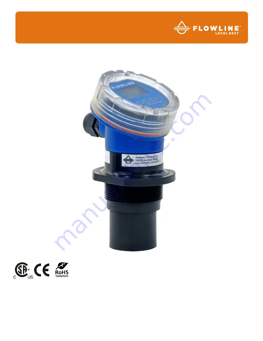
UG06 & UG12 Series Quick Start


EchoPod

®


Ultrasonic Liquid Level Transmitter 

Summary of Contents for EchoPod UG06 Series

Page 1: ...umbolt Street Los Alamitos CA 90720 p 562 598 3015 f 562 431 8507 w flowline com QS310140 Rev A2 2017 Flowline Inc All Rights Reserved Made in USA UG06 UG12 Series Quick Start EchoPod Ultrasonic Liqui...

Page 2: ...ed version only ENCLOSURE While the switch housing is liquid resistant the EchoPod is not designed to be operational when immersed It should be mounted in such a way that the enclosure and transducer...

Page 3: ...al powe is 15 play and unp tor on the cir per terminals correspond Fob to Red to Black W to White G to Green inal screws w o your PC s U al a PC sof quires conne E w flowline co B storage spa ection t...

Page 4: ...the location of the sensor with respect to fittings risers dome tops and bottoms and identify where the measurements are taken from the sensor The HEIGHT and FILL H settings determine the 4 20mA span...

Page 5: ...Confirm units for use in Sensor Height and Fill Height settings Sensor Height Sets the location for 4mA It is based on the distance from the Empty level position bottom of tank to the Measurement loc...

Page 6: ...Cal software please refer to the WebCal manual located at flowline com webcal software Before configuration can be completed You must click the Write to Unit button to save the settings to the unit Th...

Page 7: ...E THE TANK Measuring the tank is one of the most important aspects in configuring the sensor When measuring the tank take into account the location of the sensor with respect to fittings risers dome t...

Page 8: ...o return to the TOP LEVEL MENU 9 Select RUN to return to Operational Mode Note The Height and Fill Height settings also determine the 4 to 20 mA current span The Height setting determines the 4mA posi...

Page 9: ...larger bulkhead fitting such as the LM52 3890 with a reducer bushing such as the LM52 2400 Use a flange with a 2 thread such as the LM52 2850 Weld a plastic 2 half coupling to the tank top Mounting i...

Page 10: ...he minimum diameter of the pipe is 3 minimum 4 for the UG12 series Larger diameter pipes can be used The pipe should be attached with a coupling or tank adapter and reducer bushing Avoid the use of mu...

Page 11: ...installation must have a redundant backup safety system installed Wiring should always be completed by a licensed electrician The sensor must be chemically compatible with the application Design a fa...

Page 12: ...2 have been subjected to electrical mechanical or chemical damage due to improper accidental or negligent use 3 have been modified or altered 4 anyone other than service personnel authorized by Flowl...

Reviews: