205288 D/E
10
E
4.0 Transport
ATTENTION! Always check delivery for completeness and damage!
The carrier (forwarder or railway) is to be informed immediately in case of transport damages.
(s. yellow leaflet)
5.0 Setting up the machine
The drill should be set up on a solid base and aligned using a spirit level. If the machine is to be bolted to the base,
ensure that the base plate does not warp in the process. Use of vibration damping elements is recommended.
6.0 Installation
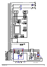
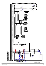
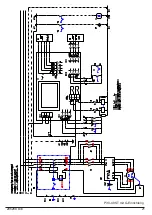
The machine has been installed ready for use. Please check whether type of current, current voltage and fusing agree
with the prescribed values. There must be a protective ground terminal. Mains fusing 16 A.
Attention! Take notice of the right rotation (right-hand) of spindle
.
7.0 Commissioning
The parts with rust-inhibiting coating should be cleaned carefully. The column should then be lubricated. The table should
be moved several times since condensation may have formed in the table guide.
8.0 Operating and indication elements
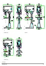
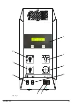
(max. equipment) see figure 2
1. main switch
2. polarity/reverse switch
3. drilling speed indicator/ drilling depth indicator
4. switch drilling/tapping
5. emergency push button
6. coolant on/off
7. lighting on/off
8. switch for power-operated height adjustment of machine (option)
9. switch for power-operated table adjustment (option)
9.0 Operating
For starting/stopping the machine switch on/off the main switch. Hereto first unlock the emergency push button
(optional). The electrical drill guard must be closed (safe position).
If present use the polarity/reverse switch to select the right speed level, now you can change from spindle speed
step 1 (right-hand) into spindle speed step 1 (left-hand) e.g. for tapping. The switch drilling/tapping (option) selects the
direction of the spindle, with the switch drilling/tapping (option) choose the working process.
10.0 Speed indication
10.1 On machines
without
a digital speed indication the set speed will be shown on a scale at the shifting lever.
Machines with variable speed drive are preadjusted to speed level 1.
10.2 On machines
with
a digital speed indication the set speed will be shown exactly on the display (accuracy 10 rpm).
11.0 Speed change
11.1 On machines with a
variable - speed drive
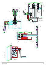
open the hood (skrew B), unmount indicator, clamping lever, shift lever
and left-hand hood (skrew A). Untension the belt by unclamping the motor holder and switch belt to the corresponding
belt disc. Assembly in reverse order.
11.2 On machines with a
mechanical
infinitely variable - speed drive
change the speed by swivelling the shifting
lever when the machine is running.
11.3 On machines with a
electronical infinitely variable - speed drive
change the speed by turning the
potentiometer.
12.0 Drilling depth indication
12.1 On machines
without
a digital drilling depth indication the drilling depth is shown on a scale.
12.2 On machines
with
a digital drilling depth indication the set drilling depth is shown digitally.


