background image

8

GB

IE

CY

Assembly instructions

  Always disconnect the tool from the 

mains before conducting any work on it. 

Scope of delivery

Carefully remove the tool from the packaging 

and check that the following parts are com-

plete:

•  Motor housing with tines and frame tubing

•  Right-hand fork with dead-man lever and 

permanently fi xed mains cable

•  Left-hand fork grip

•  Plastic cross-plate with cable guide

•  Assembly tools, cable clips and belt clip

•  User manual

  While assembling the tool, make sure 

that the mains cable does not become 

caught and has enough slack.

Fitting the grip tubing

B

  1.  Push the two fork grips (1a/1b) into 

the plastic cross-plate (3), and screw 

the plate into the corresponding holes 

in the grip tubing from behind using 

the bolts provided (13).


2.  Push the mains cable into the cable 

guide (14) on the cross-plate.


3.  Position the assembled grip frame 

with the tube ends on the left and 

right-hand sides at the lower frame 

tubing (5).


4.  Push the two fi nger bolts into the 

holes from the outside inwards, and 

tighten them with the wing nuts (4).


5.  Fasten the mains cable with the cable 

clips supplied:


  - Large cable clip (6a) above the 

cross-plate


  - Small cable clip (6b) at the frame 

tubing.

Operation

  Observe noise-abatement laws and lo-

cal by-laws.

Switching on and off

  Note: Before switching the tool on, 

make sure that the tool is not touch-
ing any other objects and hold it 

fi rmly in both hands. 

C

  1.  Plug the tool into the extension cable.


2.  Loop the end of the extension cable 

and hang it onto the cable tension relief 

(16) to ease the tension on the cable.


3.  Plug the tool into the mains.


4.  Hang the extension cable onto the belt 

clip (12) and fasten it to your trouser 

belt.


5.  To switch on, press the safety release 

catch (17) and then squeeze the dead-

man lever (18). Release the safety 

release catch (17).


The tines will begin to rotate and dig 
themselves into the earth.


6.  To switch off, release the dead-man 

lever (18).

  Warning! The tines will continue to 

turn for a few seconds after the tool 
has been switched off. Do not touch 
the rotating tines – injury hazard!

Operating instructions

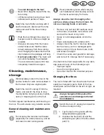
  Always keep a fi rm grip on the tool 

with booth hands and watch your 
feet.
The tines may cause an accident.
Be careful while moving backwards 
– danger of tripping!


Do not touch the gearbox, as it may 
become hot during operation – dan-
ger of burns!

Summary of Contents for FGH 700/9 series

Page 1: ...GARDEN CULTIVATOR GARDEN CULTIVATOR Operation and Safety Notes FGH 700 9...

Page 2: ...Before reading unfold the page containing the illustrations and familiarise yourself with all functions of the device GB IE CY Operation and Safety Notes Page 4...

Page 3: ...10 9 8 7 6b 4 5 3 1a 2 13 3 13 14 4 4 6b 19 20 21 23 22 16 18 17 12 12 11 1a 5 10 6a 6a 11 1b 1b...

Page 4: ...of electrical equipment in household waste Contents Safety notes 4 Symbols 4 General safety notes 5 Functional description 7 Functional parts 7 Intended purpose 7 Assembly instructions 8 Scope of del...

Page 5: ...soles and strong long trousers Do not use the tool barefoot or wearing open toed sandals To prevent injury from the tines only switch the tool on in its working position Examine the tool beforehand e...

Page 6: ...ect the tool from the mains before changing the area you are working on Never leave the tool unattended where you were using it Switch the tool off wait for the tines to stop moving and disconnect the...

Page 7: ...wheels that automatically dig themselves into the ground The aluminium frame can be folded to aid storage Please refer to the following descriptions for the function of the controls The major functio...

Page 8: ...mains cable with the cable clips supplied Large cable clip 6a above the cross plate Small cable clip 6b at the frame tubing Operation Observe noise abatement laws and lo cal by laws Switching on and...

Page 9: ...pecially not under pressure and do not clean it under running water Wear protective gloves when carrying out maintenance and cleaning work on the tool to avoid injury from cuts Always clean the tool t...

Page 10: ...arantee period of thirty six months A shorter guarantee period of 12 months shall apply for com mercially used and replacement tools ac cording to statutory regulations If you have a justi ed guarante...

Page 11: ...k our service cen tre for details Technical speci cations FGH 700 9 Electric Tiller Motor power input 710 W Mains voltage 230V AC Mains frequency 50 Hz Working width 360 mm Max working depth 180 mm Nu...

Page 12: ...A2 2006 EN 50366 A1 2006 EN 55014 1 A2 2002 EN 55014 2 A1 2001 EN 61000 3 2 A2 2005 EN 61000 3 3 A2 2005 We additionally con rm the following in accordance with the 2000 14 EC emissions guideline Guar...

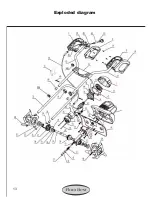
Page 13: ...13 Exploded diagram...

Page 14: ...rvice Center DES Ltd Unit 14 15 Bilston Industrial Estate Oxford Street Bilston WV14 7EG Tel 0870 787 6177 Fax 0870 7876168 Email grizzly deslimited com From Ireland Tel 0044 870 787 6177 Fax 0044 870...

Page 15: ......

Page 16: ...Last Information Update 11 2008 Ident No 76005517112008 6 IAN 41803 Grizzly Gartenger te GmbH Co KG Am Gewerbepark 2 D 64823 Gro Umstadt...

Reviews: