(877) 356-5463 | (p) 330-331-7331 | (f) 330-331-7172 | www.FLO-CORP.com | © 2017 FLO-CORP | REVA 1116
1
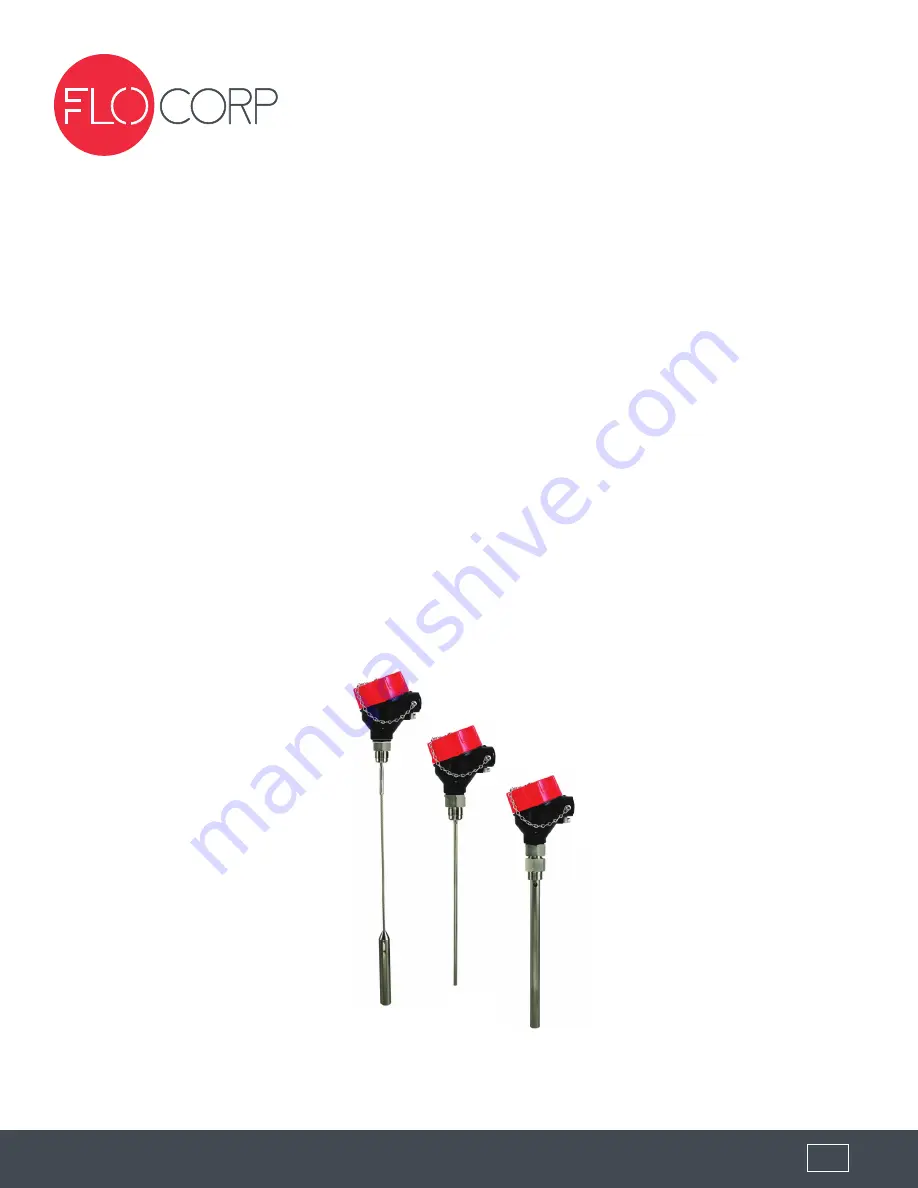
TRACER 1000
™
LTT1
GUIDED WAVE RADAR LEVEL TRANSMITTER
OPERATING INSTRUCTIONS
Page 1: ...877 356 5463 p 330 331 7331 f 330 331 7172 www FLO CORP com 2017 FLO CORP REVA 1116 1 TRACER 1000 LTT1 GUIDED WAVE RADAR LEVEL TRANSMITTER OPERATING INSTRUCTIONS...
Page 2: ...zed Personnel All operations described in this operating instructions manual must be carried out only by trained specialist personnel authorized by the plant operator During work on and with the devic...
Page 3: ...8 Resolution 04 Probe Type 316 SS Rod 1 4 Dia Coated Rod 3 8 Dia 316 SS Coaxial 3 8 Dia Wire Cable 1 2 Dia Probe Length L 316 SS Rod 2 41 120 316 SS Coaxial 0 120 Wire Cable 2 41 480 Length must be sp...
Page 4: ...wells Bypass chambers and stilling wells Limited headroom for installation Limited headroom for installation Tall tanks Tall tanks MEDIA CHARACTERISTICS MEDIA CHARACTERISTICS Bulk solids Bulk solids...
Page 5: ...80 PSIG Preparation FLO CORP s Tracer 1000 level transmitters are ready to install as is and are completely pre configured per the application data sheet or customer application information at time of...
Page 6: ...is made of 316L Stainless Steel 1 4 diameter The Rod probe can be ordered with an optional teflon isolation sleeve and connections Both configurations have a threaded female connection on one end and...
Page 7: ...und it will be connected to is exactly equal to the ground potential of the transmitters power If there is a ground offset you will potentially experience faulty signal outputs The grounding screw is...
Page 8: ...877 356 5463 p 330 331 7331 f 330 331 7172 www FLO CORP com 2017 FLO CORP REVA 1116 8 Figure 3 Wiring Diagram Interconnecting Wiring to DigaCom 2000 Typical 3 Wire Connection...
Page 9: ...877 356 5463 p 330 331 7331 f 330 331 7172 www FLO CORP com 2017 FLO CORP REVA 1116 9 External Power Wiring To Input ie PLC External Powered Wiring To DigaCom 2000 Level Monitor...
Page 10: ...877 356 5463 p 330 331 7331 f 330 331 7172 www FLO CORP com 2017 FLO CORP REVA 1116 10 PNP Output Wiring...
Page 11: ...ONLY BLUE Indicates the DIP switch positions through which groups of functions are selected example all functions related to the analog current output or the switching output GRAY Indicates the DIP sw...
Page 12: ...w seconds while the disturbance signal scan is being performed Once the scan is completed successfully the LED will return to blinking alternately green and red If this is the only function you want t...
Page 13: ...the tank to the level of the tank where you want the switch point to be activated Next set the following DIP switch to the ON 1 position 8 6 3 All other switches should be in the off position The LED...
Page 14: ...surface of the connection thread The probe length is an important mechanical dimension which is needed to make sure the probe physically fits into the tank at the anticipated mounting location The pr...
Page 15: ...by returning to the RUN mode Tracer still reading high Increase upper deadband to medium 7 4 This may require adjustment of 20mA set point 1 2 Tracer 1000 erratic output throughout the span of the pro...
Page 16: ...by returning to the RUN mode Tracer still reading high Increase upper deadband to medium 7 4 This may require adjustment of 20mA set point 5 2 Tracer 1000 erratic output throughout the span of the pro...
Page 17: ...h button Verify output by returning to the RUN mode Tracer still reading high Increase upper deadband to medium 7 4 This may require adjustment of 20mA set point 9 2 Tracer 1000 erratic output through...
Page 18: ...struct your FLO CORP Model Number Simply match the category number to the corresponding box number Example LTT1 RN6 01 120 N 000 Tracer 1000 GWR Level Transmitter with 316 SS Rod Probe Type NEMA 6 Enc...