


5.3
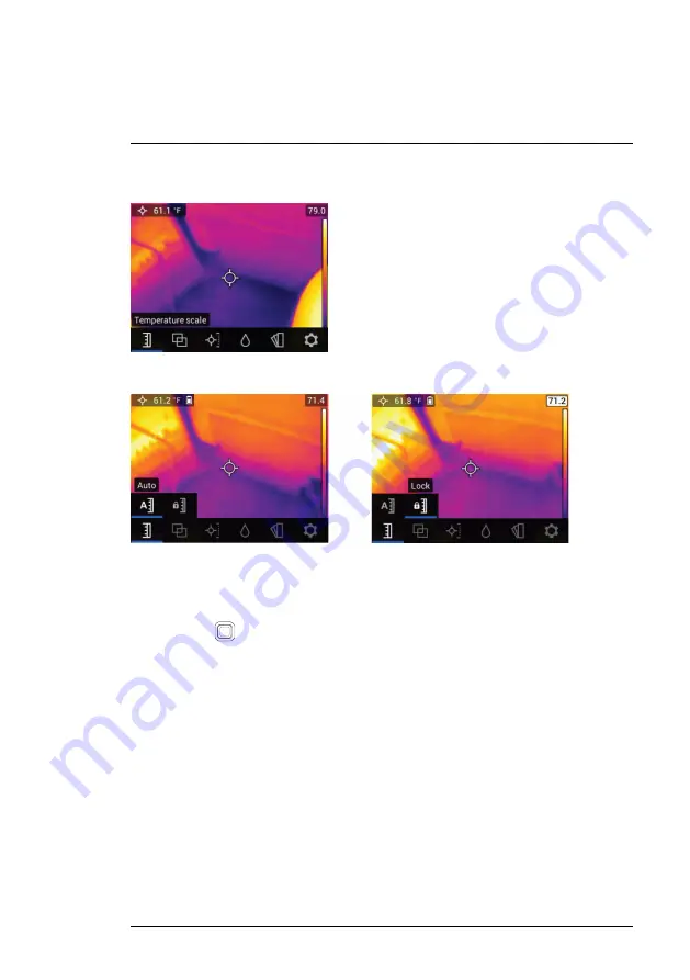
Temperature Scale Menu
Figure 5.2
Accessing the Temperature Scale Menu
Figure 5.3
Selecting AUTO or LOCK Scaling
The Temperature scale menu allows you to select Automatic (Auto) or Lock
scaling. Use the navigation buttons to move to the desired setting and then
press
Select
to confirm.
In Automatic mode, the MR265 automatically selects the temperature range
for each thermal image, based on the highest and lowest temperatures de-
tected. In Lock mode, you can ‘lock in’ a particular thermal image’s tempera-
ture range and use this locked range for subsequent thermal image
comparisons. This locked range does not change, regardless of the highest
and lowest temperatures detected for the subsequent images. See
Section
8–2
Automatic and Lock Scaling
for more information.
To release the Lock mode, simply select the Auto mode as described above.
#NAS100070; r. AB/77165/77326; en-GB
9


