


Installing M-Series Camera Systems
432-0003-60-12 Version 100
May 2017
14
Caution!
Proper Grounding
Caution!
Use the green wire to provide chassis ground for cable lengths under 2 m (6 ft). For longer cabling,
a bonded grounding scheme with a common ground between the chassis ground and electrical
return, with the connection made as close as possible to the negative terminal of the battery using
a low-resistance grounding strap connected directly to one of the M6 mounting bolts. Failure to
provide this connection may result in electrical interference between camera and other shipboard
electronic systems.
Connecting Power
The camera itself does not have an on/off switch. Generally the M-Series camera will be
connected to a circuit breaker and the circuit breaker will be used to apply or remove power to the
camera. When power is supplied, the camera will be in one of three modes: Booting Up. Standby,
or Powered On. The
M-Series Operator’s Manual
has detailed information about powering and
operating the camera.
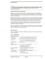
Install a fuse in line with the power connection to
protect the camera from power surge or short
circuit. Table 1.2 applies to all camera models.
The installer must use power cable wires that are
sufficient size gauge or diameter for the supply
voltage and total load (camera and length of cable
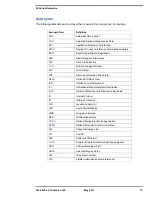
TABLE 1.1
Connections Quick Reference
Cable Label
Wire
Comment
Power
Red
Nominal 12 Vdc / 24 Vdc
Absolute range 10 Vdc to 32 Vdc
50 watt maximum
Black
DC return
Green
Chassis ground
IR
F-Style Coax
Thermal camera video only
VIS/IR
a
a.
VIS/IR cable is only present on dual payload models.
F-Style Coax
Use if only one display
JCU
RJ45
Use shielded Ethernet cable
Ensure power is removed including from PoE power sourcing equipment before installation or
removal of system components. Damage to equipment may result.
During installation, ensure the cables exiting the bottom of the camera are not in contact with
sharp edges, do not bend at sharp angles, and are not pinched between the bottom of the
camera and the mounting surface. Do not pull on the cables with excessive force.
It is recommended that any built-up triboelectric charge on the Ethernet cable should be
discharged
before
connecting it to the JCU and camera. This can be accomplished simply by
pressing an ungloved finger across the Ethernet RJ45 connector of the cable for a few seconds.
Ensure the camera is properly grounded. Following best grounding practices, the camera
chassis ground should use the lowest resistance path possible.
TABLE 1.2
Fuse Recommendations
Voltage
Fuse
12 Vdc
5 amp
24 Vdc
3 amp


