

Installing Your Firefly USB3
1. Install the Tripod Mounting Bracket (optional)
The ASA and ISO-compliant tripod mounting bracket
attaches to the camera using the included screws.
2. Attach a Lens
Unscrew the dust cap from the lens holder to install a lens.
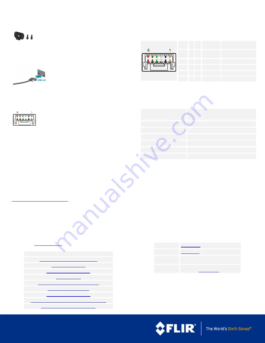
3. Connect the interface Card and Cable to the Camera
Plug the interface cable into the host controller
card and the camera. The cable jack screws can be
used for a secure connection.
When the camera is first connected, the operating system automatically installs
the camera driver. Camera drivers are available with the Spinnaker SDK
installation.
4. Plug in the GPIO connector if required
GPIO can be used for trigger, serial input output, and
strobe.
5. Confirm Successful Installation
Run the SpinView application:
Start->All Programs-> Point Grey Spinnaker-
>SpinView
The SpinView application can be used to test the camera's image acquisition
capabilities.
Changes to your camera's installation configuration can be made using the
SpinView application.
Camera Interface
USB 3.0 Connector
The camera is equipped with a USB 3.0 Micro-B connector that is used for
power, data transmission, and camera control. For more detailed information,
consult the USB 3.0 specification available from
http://www.usb.org/developers/docs/
.
General Purpose I/O Connector
The camera is equipped with a 6-pin GPIO connector on the back of the case.
Diagram
Color
1
Pin
Line
Function
Description
Orange
1
2
0
GPIO0
Non-isolated Input/Output
TXD (output) for 1.8 V UART
Black
2
2
1
GPIO1
Non-isolated Input/Output
RXD (input) for 1.8 V UART
White
3
2
GPIO2
Non-isolated Input/Output
Green
4
3
GPIO3
Non-isolated Input/Output
Brown
5
N/A
GND
Camera Power Ground
Red
6
N/A
Vout
Camera Power Output
1—GPIO cable assembly wire colors
2—Dual function pin
Status Indicator LED
LED
USB
No Light
No power
or LED is in inactive state
or LED is in error status state with no error
Blinking Green (1 blink)
USB1
Blinking Green (2 blinks)
USB2
Blinking Green (3 blinks)
USB3
Solid Green
Acquisition Started
Rapid Flashing Green
Firmware update in progress
Flashing Green and Red
General Error
10/4/2019
Names and marks appearing on the products herein are either
registered trademarks or trademarks of FLIR Systems, Inc. and/or
its subsidiaries.
© 2015-2019 FLIR Integrated Imaging Solutions Inc. All rights
reserved.
For More Information
FLIR endeavors to provide the highest level of technical support possible to
you. Most support resources can be accessed through your product's Support
page. From the
page, click on your product family and then
click the
Go to Support Page
link.
Your camera's settings and capabilities—Technical Reference or Camera Reference
Spinnaker® SDK—API Reference / Programmer's Guide
Selecting a lens for your camera
Recommended USB3 System Components
Using third-party applications from our software partners
Getting Started with Firefly-DL in Linux
Neural Networks Supported by Firefly-DL
Tips for Creating Training Data for Deep Learning and Neural Networks
Troubleshooting Neural Network Conversion Errors
Contacting Us
For any questions, concerns or comments please contact us via the following
methods:
Support Ticket
Chat
Go to the Support Page for any product on the
FLIR machine vision page and click the chat icon
Website
Find specifications, support articles, downloads on the
product page at


