


Rev:
H
Revision Date:
06/19/2012
Page 8 of 14
MAN – FD70CV-M
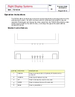
Power and Ground Wiring
22 AWG wire is recommended for Power and Ground applications.
Power/Video
Pin out for P1 (High Density DB-15 Receptacle)
Connector
P/N: M24308/2-286 or Equivalent
Crimp Contacts
P/N: M39029/57-354 or Equivalent
Pin
Number
Description
1
12-28VDC Power
2
12-28VDC Ground
3
N/C
4
Composite Video 1 - Signal
5
Composite Video 1 - Shield
6
N/C
7
Composite Video 2 - Signal
8
Composite Video 2 - Shield
9
Red Video (Pin 1 on Standard VGA)
10
Green Video (Pin 2 on Standard VGA)
11
Blue Video (Pin 3 on Standard VGA)
12
Red Ground (Pin 6 on Standard VGA)
13
Green Ground (Pin 7 on Standard VGA)
14
Horizontal Sync (Pin 13 on Standard VGA)
15
Vertical Sync (Pin 14 on Standard VGA)


