


Printed in Canada
TAC1000 Manual
June 19, 2013
Page 6
3.2
PNEUMATIC SPECIFICATIONS
Flexxaire supplies a number of pneumatic control options,
but the TAC1000-P can be operated using any air source
that meets the general specifications listed below. If your
machine has air on board then this source will be available.
If not, then a compressor will be required.
General Specifications:
Full Pitch
(default position):
0 psi (0 kPa)
Neutral Pitch
(Stop air position):
~
60 psi (413 kPa)
Reverse Pitch
(Purge position):
90 psi (620 kPa)
Max intermittent pressure:
110 psi (758 kPa)
Max continuous pressure:
90 psi (620 kPa)
4.0
HYDRAULIC LINE INSTALL
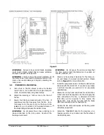
A.
Drill a hole in the fan shroud to allow the flexible
hydraulic hose to be routed into the engine compart-
ment. Secure the hose using hose clamps.
B.
No exterior bracing should be used to prevent the
rotary union from rotating. It is imperative that a
flexible connection be used.
C.
The fan is supplied with the hydraulic line attached.
Connect the line to the hydraulic source that will be
used to operate the fan. Use thread sealant on all
connections.
D.
Ensure that the hose clears all parts of the fan. If
possible, secure the hose away from the fan. Com-
mon ways to do this are to zip tie the hose to the
radiator core, or to attach it to the radiator frame or
the bolted flanges between the radiator cores.
E.
Rotate the fan by hand and check for obstructions.
A final check will be required once the hydraulic hose
has been connected to the hydraulic source. A mini-
mum of 450 PSI (3 MPa) will be required to fully re-
verse the blade pitch. Spin the fan by hand with the
blade pitch reversed and check for obstructions. Use
Figure 5 on Page 5 for clearance between the blades
and any stationary objects.
F.
Tighten the fan belts and replace all the fan guards
and safety equipment.
G.
Attach the “WARNING” label to the machine, on a
housing, guard, or any location near the fan where it
can be easily seen.
WARNING:
Do not secure the hydraulic hose so tight
as to cause a side load on the rotary union. Failure of
the bearings could result.
WARNING:
Do not secure the hydraulic hose so
loose that the hose could contact the blades due to
sudden air reversal, vibration, etc..
H.
Install the hydraulic control valve. Follow the in-
structions included with the control kit. If you did
not purchase a kit from Flexxaire, see section 4.1 for
hydraulic specifications.
4.1
HYDRAULIC SPECIFICATIONS
Flexxaire supplies a number of hydraulic control options,
but the TAC1000-H can be operated using any hydraulic
source that meets the general specifications listed below.
If your machine has hydraulics on board then this source
will be available.
General Specifications:
Full Pitch
(default position):
0 psi (0 MPa)
Neutral Pitch
(Stop air position):
~250 psi (1.7 MPa)
Reverse Pitch
(Purge position):
450 psi (3 MPa)
Maximum allowable pressure: 1000 psi (6.9 MPa)
5.0
SERVICE AND MAINTENANCE
Flexxaire’s TAC1000 fan hub is fully sealed with o-rings,
and contains a small quantity of grease. (EP00 semi-fluid
grease) As a result, the fan itself should not require any
maintenance.
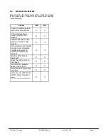
5.1
VISUAL INSPECTIONS
Under normal operating conditions TAC1000 fans do not
require any scheduled maintenance and are built to provide
thousands of hours of trouble free service. In moderate to
extreme operating conditions a visual inspection of the
moving parts in recommended from time to time to safe-
guard against fan blade damage which could lead to equip-
ment downtime and/or other damages.


