


Figure 2
27.
If using this kit with the factory 8.4” touch
screen,
follow Steps 35 through 49 and Steps
52 through 54 below.
28.
If using this kit with an aftermarket mirror /
display / NAV display,
connect Chassis
Harness male RCA to “Camera IN” on the
aftermarket mirror / display/ NAV display.
NOTE: A RCA extension may be required.
Proceed to Step 46.
29. Connect supplied 8.4” Touch Screen Jumper Harness
to RCA end of supplied Chassis Harness.
30. Use of this camera with the factory Ram 8.4” touch
screen requires activation by a Chrysler/Dodge
dealer. See below for Dealer Programming
Instructions. If possible, have the dealer “enable”
the camera option prior to installation.
31. Use a Plastic Trim Tool to remove shifter bezel and
remove two screws from under the rubber mat using
a Phillips screwdriver.
32. Use a Plastic Trim Tool to remove cup holder bezel.
33. Remove rubber mat on top of 8.4” screen to expose
two screws and remove them using a T20 Torx bit.
34. Remove rubber mat in square cubby hole to expose
one screw and remove it using a T20 Torx bit.
35. Use a Plastic Trim tool to remove radio bezel to
expose the 4 screws securing the radio head unit
and remove them using a 7mm socket.
36. Unplug all radio connectors from the radio head unit
and set radio aside.
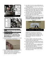
Note: If vehicle is NOT equipped with a 22-pin
radio connector (Figure 3), use supplied white
connector to complete steps 43 and 44.
Figure 3
IMPORTANT: If the white 22-pin connector is
present in the vehicle and pin 3 and/or pin 4 are
already populated, remove the terminal(s) using
Delphi terminal removal tool# 12094429 or a small
flat watch repair screwdriver and isolate with
electrical tape.
37. Locate pin position 3 on the white 22-pin radio
connector (Figure 3) and insert red terminal of the
jumper harness until it clicks securely.
38. Insert black terminal of the jumper harness into pin
position on the white 22-pin radio connector (Figure
3) until it clicks securely.
39. Connect white 22-pin connector to radio along with
all remaining connectors before reinstalling radio
head unite and all trim removed.
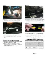
40. Route Chassis Harness behind rear cab mount and
out to the inside of the vehicle. RECOMMENDED:
Use a Wire Tie to secure Chassis Harness between
the cab and bed mount.
Remove bolt
to attach
eyelet on
Black Ground
wire from
supplied
Chassis
Harness to
Chassis
Ground bolt.
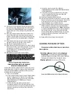
Remove
½
”
bolt attaching
Instrument
Panel
connector
mount to gain
access to BCM
pink/green
Ignition
(12v+) wire.
Pin 4 – Black terminal
Pin 3 – Red terminal


