Flavel FSCC12MN Installation And Maintenance Instructions Manual Download Page 13

Fig. 6

d)

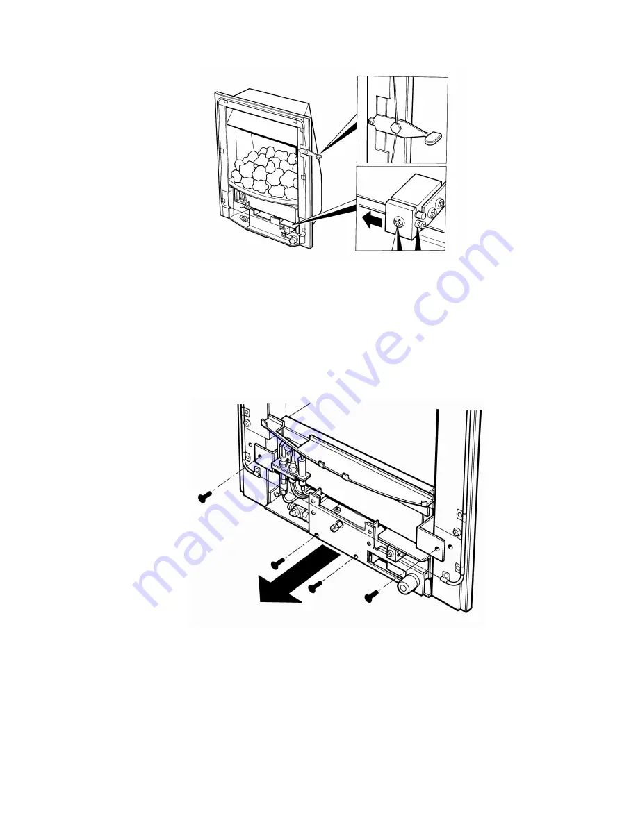
Unscrew the burner assembly fixing screws at either side of the firebox,

and the two fixing screws at the base of the fire (See fig. 7 below).

Carefully pull the base of the burner forwards from the fuel-bed

support panel. The burner can now be removed from the appliance.

Fig. 7

13

Summary of Contents for FSCC12MN

Page 1: ...EFFECT GAS FIRE Installation and Maintenance Instructions Hand these instructions to the user Model No FSCC12MN FSCC23MN FSCC42SN FSCC53SN are only for use on Natural Gas G20 at a supply pressure of...

Page 2: ...2 4 Gas Tightness Inlet Pressure SC models 19 20 Section 3 Assembling Fuel Bed and Commissioning 3 1 Assembling the ceramics and fuel bed 20 23 3 2 Lighting the appliance MC models 24 3 3 Lighting th...

Page 3: ...CC53SN 19 0 kg FSCC12MN FSCC23MN Fire box Dimensions with trim fitted Width with standard trim no spacer 480mm Height with standard trim no spacer 590mm Depth overall without fender 125mm Depth Flush...

Page 4: ...nd flues 7 B S E N 1858 Chinmeys Components Concrete Flue Blocks 8 I S 813 1996 Domestic Gas Installation Republic of Ireland No purpose made additional ventilation is normally required for this appli...

Page 5: ...150mm 1 5 FLUE CHIMNEY INSPECTION Before commencing installation a flue or chimney should be inspected to ensure that all the following conditions are satisfied 1 Check that the chimney flue only ser...

Page 6: ...ied out during commissioning of the appliance 1 6 FIRE PLACE OPENING AND CHIMNEY CATCHMENT SPACE The front opening of the fire place must be between 330 and 430 mm wide and between 550 and 570mm high...

Page 7: ...h mm Minimum Depth Required mm 330 minimum opening width 222 340 218 350 215 360 211 370 205 380 199 390 193 400 189 410 183 420 178 430 172 440 maximum opening width 168 For example if the appliance...

Page 8: ...e fire surround may be packed away from the wall using suitable non combustible board providing the installation is correctly sealed If in doubt about the suitability of the fire contact BFM Europe fo...

Page 9: ...oxygen sensing pilot This is designed to shut the fire off in the event of a partial or complete blockage of the flue causing a build up of combus tion products in the room in which the fire is opera...

Page 10: ...book and Installation book 2 2 INSTALLING THE FIRE BOX Establish which type of flue you are intending to install the fire in to 225 x 225mm 9 inch x 9 inch brick built chimneys 175mm 7 inch diameter...

Page 11: ...ted from damage and carefully lift the fire box into the fire opening then slide it back into position Check that the fire box flange fits flush to the sealing face of the fire surround or wall with n...

Page 12: ...present c Remove the burner To allow burner removal the control lever operat ing cable must be removed The control lever operating cable can be seen running across the base of the fire below the burne...

Page 13: ...g screws at either side of the firebox and the two fixing screws at the base of the fire See fig 7 below Carefully pull the base of the burner forwards from the fuel bed support panel The burner can n...

Page 14: ...g 8mm rigid tubing There must be no soldered joints within the firebox See fig 8a 8b below for suggested concealed pipe layouts Fig 8a Fig 8b Note Before breaking into the gas supply a pressure drop t...

Page 15: ...which in turn will damage the burner and control systems of the product Fig 9 below shows a correctly sealed installation Fig 9 PLEASE NOTE Seal off unused gas inlet apertures and cable fixing holes...

Page 16: ...of the cables through one of the two holes on each side of the flue outlet shroud g Position the fire carefully on the protected surface of the hearth and reach into the fire opening Thread each of t...

Page 17: ...l Refit the burner Fit the four retaining screws and check that the burner is correctly locked into position On slide control models refit the control cable To do this firstly locate the nipple on one...

Page 18: ...otherwise serious damage may be caused to the gas control valve on the fire The other firebox fixing method is as follows In installations where the cable method is not suitable e g loose masonary in...

Page 19: ...point screw for gas tightness with the appliance turned on using a suitable leak detection fluid or detector 2 4 GAS TIGHTNESS AND INLET PRESSURE SLIDE CONTROL MODELS a Remove the pressure test point...

Page 20: ...t and is not lodged on the burner See fig 13 below Fig 13 b Position the two halves of the front ceramic L H R H on the locating channel in the front ceramic ensuring it is located onto the lip on the...

Page 21: ...hey are evenly spaced Use the recess s in the front ceramic rail as a guide for placement See fig 15 below Fig 15 d Select four of the large coals and arrange behind the front row of coals ensuring th...

Page 22: ...ear of the fuelbed using the recesses in the rear of the fuelbed as a guide for placement See fig 17 below Fig 17 f Select three of the medium sized coals and arrange along the fuelbed behind the seco...

Page 23: ...tory Ceramic Fibre articles is kept to a minimum during installation and servicing we recommend that you use a HEPA filtered vacuum to remove any dust accumulated in and around the appliance before an...

Page 24: ...trol knob and turn to the off position the pilot will now be extinguished 3 3 LIGHTING THE APPLIANCE Slide Control Models a Turn on the isolation valve Depress the control lever fully downwards to the...

Page 25: ...5 10 minutes If the test indicates that spillage is occurring and the flue restrictor baffle has been fitted it should be removed and the test repeated after the fire has cooled d If spillage persists...

Page 26: ...a safe location Remove the loose coals from the fuel bed and front ceramic rail Remove the front ceramic from the rail Unscrew the two pozi driv fixing screws which secure the burner heat shield and r...

Page 27: ...t it is not possible to replace the thermocouple separately because the thermocouple position is factory set to a tight tolerance Any replacement of parts on the pilot requires a complete new pilot as...

Page 28: ...ly tension the operating cable To do this first set the control lever to the horizontal central position this is the position which creates maximum tension in the operating cable Refit the operating c...

Page 29: ...d the two inline leads from the microswitch 4 8 3 Unscrew and remove the two pozi drive screws which secure the pilot assembly to the burner Remove the pilot 4 8 4 Re assemble in reverse order and car...

Page 30: ...ush in the gap between the two lengths of p t f e sleeve Ensure that the cable is located in the retaining hole in the locking bush and tighten the screw sufficiently to retain the cable but still all...

Page 31: ......

Page 32: ...55640 Slide Valve SC models B 40890 Ignition Wire SC models 750 14340 Spark Generator SC models B 13540 Microswitch SC models 750 15600 Piezo Igniter MC models B 1320 Ignition Wire MC models B 14340 G...

Reviews: