


2.9
MAKING THE GAS CONNECTION / PRESSURE TESTING
THIS APPLIANCE IS INTENDED FOR USE ON A GAS SUPPLY WITH
A GOVERNED METER.
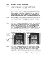
2.9.1
The gas connection should be made to the appliance inlet elbow to
using 8mm rigid tubing.
2.9.2
Remove the pressure test point screw from the inlet elbow and fit a
manometer.
2.9.3
Fit the batteries as per section 2.10, turn on the main gas supply and
carry out a gas tightness test. Light the fire (see section 3.2 for
instructions).
2.9.4
Check that the gas pressure is
20.0 mbar (+/- 1.0mbar) 8.0 in w.g.(+/-
0.4 in w.g.).
Turn off the fire, remove the manometer and refit the
pressure test point screw. Check the pressure test point screw for gas
tightness with the appliance turned on using a suitable leak detection
fluid or detector.
2.10
FITTING THE BATTERIES.
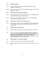
2.10.1
The product is supplied with a battery pack that is positioned at the front
left hand side of the fire as shown below in figure 12
2.10.2
Locate the battery pack by lifting away the lower infill, remove the screw
that holds the cover onto it and fit the 4 off AA sized batteries supplied
in the loose items pack.
Fig. 12
16


