


37 |
P a g e
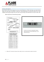
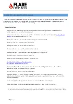
CHIMNEY PATH INSTALLATION AND PLANNING
Before vent installation, the installer should read these instructions to ensure the proper vent configuration has been selected.
To calculate the vent runs, use the following tables and instructions. Please note that power vent runs are model (burner)
specific. Use the tables below to calculate the restrictor setting.
General Instructions
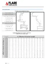
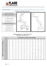
•
Diagonal runs have both vertical and horizontal vent aspects when calculating the effects. Use the rise for the
vertical aspect and the run for the horizontal aspect.
•
Various combinations of vent runs may be used. Refer to the tables below based on Fireplace size.
for clarification on how to use the table.
•
The numbers in the table represent the restrictor setting based on the vent path.
•
Symbol “x” in the table means the path is not allowed.
•
Setting the restrictor to 1 means there is no restriction.
•
Numbers in the table represent the restrictor setting to be set.
•
Document the restrictor setting configuration prior to leaving the installation site.
•
The tables apply to both NG (Natural Gas) and Propane.
•
Minimum 3 ft vertical run (A) required before any bend or turn.
o
See Flare Front and Flare See Through exception.
o
See Flare 50 & 60 5x8 table for exception
•
A maximum of
four
90º vent elbows are allowed in the vent run. Any configuration with more than 4 elbows
requires vent review and approval from Flare Fireplaces.
•
Two 45º elbows may be used in place of one 90º elbow.
•
The tables represent
the manufacturer’s guideline based on t
esting and design. Additional external factors may
affect the restrictor choice needed. If flame appears to be not typical, please contact Flare Fireplaces for restrictor
size recommendations.
•
Use the empty table in the page below to document and calculate the installation vent path.
•
Any venting pathway that does not appear the tables below require approval from Flare Fireplaces.
For optimum performance and flame appearance, keep the vent length to a minimum and limit the number of elbows.
Summary of Contents for Corner Right & Left 120
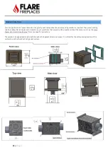
Page 65: ...65 P a g e COMBUSTIBLE FINISHING MATERIAL CLEARANCES ...
Page 71: ...71 P a g e EXAMPLES OF HEAT RELEASES ...
Page 77: ...77 P a g e ELECTRIC AND CONTROL ELECTRIC DIAGRAM SCREEN MV MV PV PV ...
Page 78: ...78 P a g e ELECTRIC DIAGRAM DOUBLE GLASS OR PV Double Glass Fan Plug No use MV MV PV PV ...
Page 80: ...80 P a g e ELECTRIC DIAGRAM PV SYSTEM Ports 49 47 are connected to J6 on fireplace main board ...