


56 |
P a g e
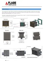
TV INSTALL RECESS
–
45 DEGREE ELBOW ON TOP OF THE UNIT
When planning a TV recess, clearance to the vent in
the chase is critical and needs to be a minimum of 1” to the non
-combustible
recessed wall. This is to prevent heat from radiating from the vent to the recessed wall and being transferred to the TV.
Due to the central location and diameter of the vent (8 inches) on our front facing & see through models, one of the following
solutions may be necessary to maintain the clearance requirement:
1.
Television recess should be 4” –
6
” inches deep, 12” from the top of the fireplace glass, which will bring the front
wall out and allow for space to recess also the TV. See an example of this on the
any deeper than 9” as
it will hinder air flow & damage the TV.
2.
Install two 45 elbows directly above the fireplace followed by a minimum 4 ft vertical vent rise. The two small
elbows will move the vertical section back 5 5/8”. Note that the 1
-inch clearance from the vent applies also to the
back non-combustible wall.
3.
Do not use any elbow with an angle larger than 45 degrees.
4.
A 4 ft minimum vertical vent must be used after the two 45-degree elbows.
5.
Note: Max recess of TV cavity should not exceed 6”. Recesses exceeding this dimension run the risk of creating a
shelf and hindering air flow above unit, resulting in a wall that may overheat.
6.
Above vent path should be used for Flare Front and Flare See Through only.
4x6
5x8
Offset
Rise
Offset
Rise
5”
13 1⁄2”
5 5⁄8”
15 3⁄8”
Summary of Contents for Corner Right & Left 120
Page 65: ...65 P a g e COMBUSTIBLE FINISHING MATERIAL CLEARANCES ...
Page 71: ...71 P a g e EXAMPLES OF HEAT RELEASES ...
Page 77: ...77 P a g e ELECTRIC AND CONTROL ELECTRIC DIAGRAM SCREEN MV MV PV PV ...
Page 78: ...78 P a g e ELECTRIC DIAGRAM DOUBLE GLASS OR PV Double Glass Fan Plug No use MV MV PV PV ...
Page 80: ...80 P a g e ELECTRIC DIAGRAM PV SYSTEM Ports 49 47 are connected to J6 on fireplace main board ...