


Scopes & VU Meters Menu
Scopes & VU Meters Menu Organization
*NOTE: The Scope & VU Meters
Menu only sets your Waveform, Vec-
tor, & Audio Level Meter display
preferences. To toggle the onscreen
display of your configured Scopes &
VU Meters profiles assign the
Scopes & VU Meters profiles to spe-
cific keys. See the
Function Menu
section of this manual for more de-
tails.
18
© 2011 Flanders Scientific, Inc.
Scopes & VU Meters Menu Functions
Scopes & VU Meters Profile 1, 2, 3
The Scopes & VU Meters menu allows you to setup three Scopes & VU Meters Profiles, each capable of stor-
ing all of the configurable settings found on the Scopes & VU Meters Menu. To configure a Profile simply se-
lect the Profile number, 1 through 3, from the top of the Scopes & VU Meters menu page. Once you have
selected the desired profile number any settings you change will become associated with that profile number.
Changing from one profile to another from the Scopes and VU Meters menu will automatically recall your last
settings for that profile. Once you have configured your Scopes & VU Meters profiles you can assign a spe-
cific function key to a particular profile, which allows you to instantly switch between different types of Scope
and/or VU Meters modes without having to go back into the onscreen menu.
Window 1 & Window 2
Two scope windows can be displayed simultaneously so you can view any two of the following modes at the
same time: Luminance (Standard Waveform), Vector Scope, RGB Parade, GBR Parade, RGB Overlay,
YCbCr, YCbCr Overlay, Column (YRGB Peak), Histogram, Color Histogram, RGB Histogram, Audio Phase,
and Vertical Audio Level Meter (PPM). Please note that displaying two Scope Windows at the same time will
cause the Scopes to update more slowly than displaying just one Scope Window. To display just one scope
Window select OFF in the secondary window selection. An additional audio level meter mode called horizon-
tal audio level meter is also selectable. This mode displays VU meters horizontally across the top of the
screen, but cannot be used in conjunction with any other Scope modes.
Helpful Hint: Waveform Intensity
can be increased by turning the H POS rotary knob while waveform is on and Vector Scope Gain can
be adjusted with the V POS rotary knob.
A Source ID function may also be enabled for Window 1 or and
can show the Source ID set on the OSD menu, the UMD ID set by remote control, and current tally activation.
Waveform Position
Use the Waveform Position toggle to select in what area of the screen you would like your Scopes to be dis-
played.
Scopes Stack
Use this option to select whether the Scope Windows are stacked vertically or positioned horizontally next to
each other when utilizing two Scope Windows.
Waveform Scale
This option allows you to choose what type of scale is used on the Waveform Monitor. You may select from
V Level (for a voltage based scale), IRE Level (for an IRE based scale 0-100), or Digital Level (for a 8 bit digi-
tal level based scaled, 0-255).
Alignment Level
Allows audio level meter alignment level to be set to –18dBFS or –20dBFS.
Back to Table of Contents
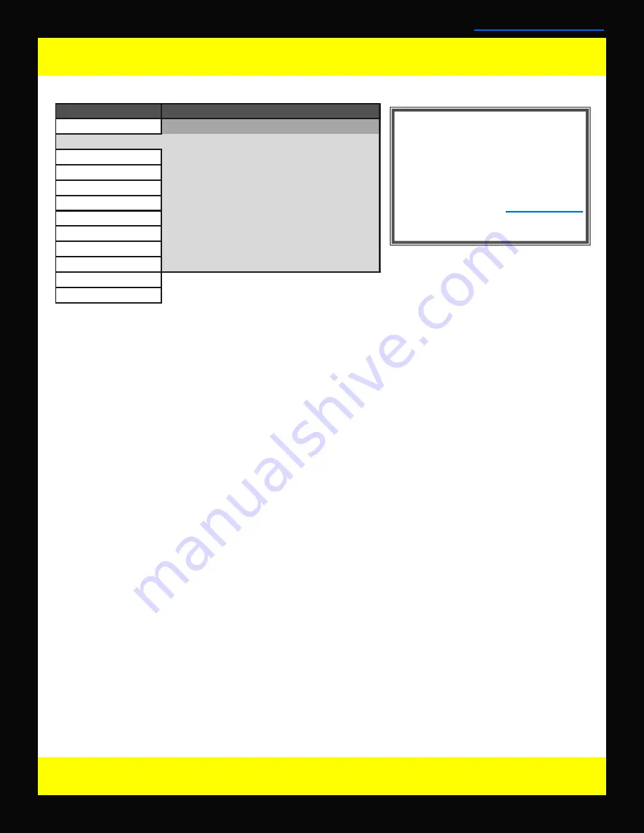
Main Menu
Function
Scopes & VU Meters
Profile 1
Scopes & VU-Meters
Window 1
Luminance
Video
Window 2
Vector
Audio
Waveform Position
Bottom Right
Marker
Scopes Stack
Horizontal
System
Waveform Scale
IRE Level
Alarm
Audio Display Mode
Pairs
OSD
Alignment Level
-18 dBFS
GPI
Permitted Max Level
-9 dBFS
Display Alignment
Audio Display Channels
1-16
System Status
Support
Scopes & VU Meters


