


VESDA-E VEU-A10 Product Guide
www.xtralis.com
9
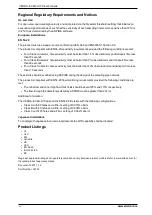
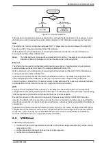
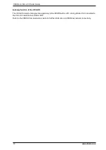
Use USB
Use WiFi
or Ethernet
Initial
Configuration
Monitoring and
Configuration Updates
Connection
Usage?
Figure 2-8: Connection Method
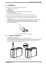
The physical communication ports are located on the main board inside the detector. It is necessary to open
the front door in order to access these ports. Refer to Section 7.2 for information on opening the front door.
USB
The USB port is used for configuration purposes ONLY. It allows direct connection between the VEU-A10
detector and a PC or laptop running the Xtralis VSC software.
Refer to Section 4.3.4 for information on connecting the USB lead, and Section 5.1.2 for information on
creating connection profiles in Xtralis VSC.
Note:
The USB port must not be used for permanent field connection. For example, do not use a USB to
Ethernet or USB to Wifi adaptor to connect the detector to a LAN using USB.
Ethernet
The Ethernet port is used for configuration and/or monitoring purposes. It enables direct or routed network
connection between the detector and a PC or laptop installed with Xtralis VSC.
Refer to Section 4.3.4 for information on connecting the Ethernet lead, and Section 5.1.2 for information on
creating connection profiles in Xtralis VSC.
A password is required to access the detector via ethernet connection. It is initially set using Xtralis VSC
during configuration with the USB port, and the user is required to enter it when creating an Ethernet
connection profile in Xtralis VSC. It is also necessary to enter additional PIN codes to access administrative
and distributor functions. Refer to Section 5.3 on page 56 for further information.
WIFI
The WiFi module provides wireless connection of the detector to the building network for the purpose of
configuration and secondary monitoring with Xtralis VSC. The VEU-A10 is joined to a wireless network during
initial configuration and remains connected while the access point is available.
Successful connection of the detector to the specified network is indicated by the WiFi LED inside the
detector. The detector is then accessible using a device that is connected to the same access point that the
detector is connected to, or a device that is joined to the same network as the access point that the detector is
connected to.
A password is required to access the detector via WiFi connection. It is initially set using Xtralis VSC during
configuration with the USB port, and the user is required to enter it when creating a WiFi connection profile in
Xtralis VSC. It is also necessary to enter additional PIN codes to access administrative and distributor
functions. Refer to Section 5.3 on page 56 for further information.
2.6
VESDAnet
A VESDAnet network allows:
l
the VEU-A10 detector to report alarms and faults to a Fire Panel using a remote display module, remote
relay module or HLI.
l
configuration and monitoring of devices from a central computer.
l
connection to a reference detector.
Summary of Contents for VESDA-E VEU-A10
Page 1: ...VESDA E VEU A10 Product Guide November 2018 Document 22077_12 Part Number 30334 ...
Page 2: ......
Page 10: ...VESDA E VEU A10 Product Guide 4 www xtralis com This page is intentionally left blank ...
Page 22: ...VESDA E VEU A10 Product Guide 16 www xtralis com This page is intentionally left blank ...
Page 54: ...VESDA E VEU A10 Product Guide 48 www xtralis com This page is intentionally left blank ...
Page 82: ...VESDA E VEU A10 Product Guide 76 www xtralis com This page is intentionally left blank ...
Page 106: ...VESDA E VEU A10 Product Guide 100 www xtralis com This page is intentionally left blank ...
Page 110: ...VESDA E VEU A10 Product Guide 104 www xtralis com This page is intentionally left blank ...
Page 116: ...VESDA E VEU A10 Product Guide 110 www xtralis com Z zone 59 61 79 105 ...


