


Page 9
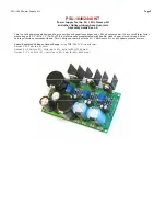
PSU-1848 Power Supply Kit
Step 3. Solder the bridge rectifiers, RECT1 and RECT2. These are the small circular components that have a “chopped-off” side.
Note the proper orientation. Follow the guide printed on the PCB.
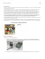
Step 4. Solder LED1 and LED2. (Note: You may wire instead LED2 to a front panel LED indicator lamp, or use the LED that comes
in the Power-Transformer Kit).
The LONG LEG of the LED should be inserted at the bottom hole.
Step 5. Solder all small electrolytic capacitors. (C3, C4, C14, C15, C16, C17)
Step 6. Solder the trimmer resistors, R3, R6, R7. Note orientation of trimmer resistors.
Step 7. Solder the medium sized capacitors C6, C7.
Step 8. Solder capacitors C8, C9.
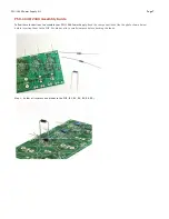
Step 9. Solder capacitors, C1 and C18. These are snap-in type capacitors. You may need to do a slight twising motion when
inserting it into the holes.
Step 10. Solder voltage regulators IC1, IC2, IC3. For aesthetic reasons, keep all their height at the same level. The flat side (i.e.
metal side) of the regulators should be facing out towards the top edge of the PCB.
Step 11. Install TO-220 heatsinks to your regulators. Use small nut and bolts to fasten the heatsinks to the regulators. You don’t
need to install insulators. Just make sure the 3 heatsinks do not touch each other, or the metal part of your case.
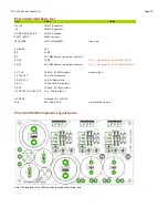
Step 12. Wire the PCB to your power transformers. See the PSU-1848 Wiring Guide below.


