background image

18

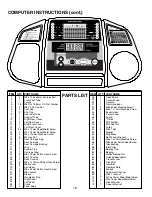
COMPUTER INSTRUCTIONS (cont.)

PARTS LIST

ITEM

1
2
3
4
5
6
7
8
9

10

11

12
13
14
15
16
17
18
19
20
21
22
23
24
25
26
27
28
29
30
31
32
33
34
35
36
37

QTY.

4
1
1

18

4
2
2
1
1
1
1
1
1

24

2
6
6
1
1
2
1
1
1
8
1
2
8
8
1
2
6
2
2
1
1
1
2

PART NAME

M8 x 1.25 x 60mm Carriage Bolt
Front Foot Tube
Frame
M8 ID x 18.8mm OD Flat Washer
M8 x 1.25 Cap Nut
Foot Cap
End Cap
Rear Foot Tube
Support Tube
Right Rear Cover
Left Rear Cover
Right Front Cover
Left Front Cover
M4 x 12mm Sheet Metal Screw
M4 x 16mm Sheet Metal Screw
M5 x 115mm Machine Screw
M5 Hex Nut
Seat Carriage Plug
Seat Carriage
Seat Carriage Bushing
Grip
Square Plug
Carriage Tube
M8 x 15mm Button Head Screw
Seat Cushion
Back Cushion
M6 x 1 x 12mm Phillips Head Screw
M6 Washer
Handlebar
M8 x 45mm Button Head Screw
M8 Locknut
Sleeve
Handlebar Plug
Right Pedal
Left Pedal
Crank
Pedal Strap

ITEM

38
39
40
41
42
43
44
45
46
47
48
49
50
51
52
53
54
55
56
57
58
59
60
61
62
63
64
65
66
67
68
69
70
71
72
73

QTY

.

1
1
1
1
2
8
1
1
1
1
2
2
1
6
1
1
1
1
1
1
1
2
2
1
1
1
1
1
1
2
2
1
3
2
1
1

P

ART NAME

Reed Switch
Console Tube
Console
Front Handlebar
M8 x 60mm Machine Screw
M6 x 1 x 10mm Machine Csrew
Book Holder
Center Cover
Spring
"V" Belt
M10 Washer
M10 Cap Nut
Pulley
M6 x 1 Nut
Magnet
Mag Brake
Belt Tension Bracket
M6 x 1 x 20mm Machine Screw
M8 x 45mm Button Head Screw
Idler Bushing
Idler Pulley
Bearing Cup
Bearing
Slotted Bearing Nut
Notched Bearing Nut
Crank Washer
Crank Nut
Gear Box
Gear Box Plate
Eyebolt
Adjustment Channel
M6 x 1 Locknut
M3.5 x 15mm Sheet Metal Screw
M4 x 16mm Sheet Metal Screw
Crank Washer
Owner's Manual

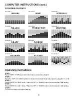
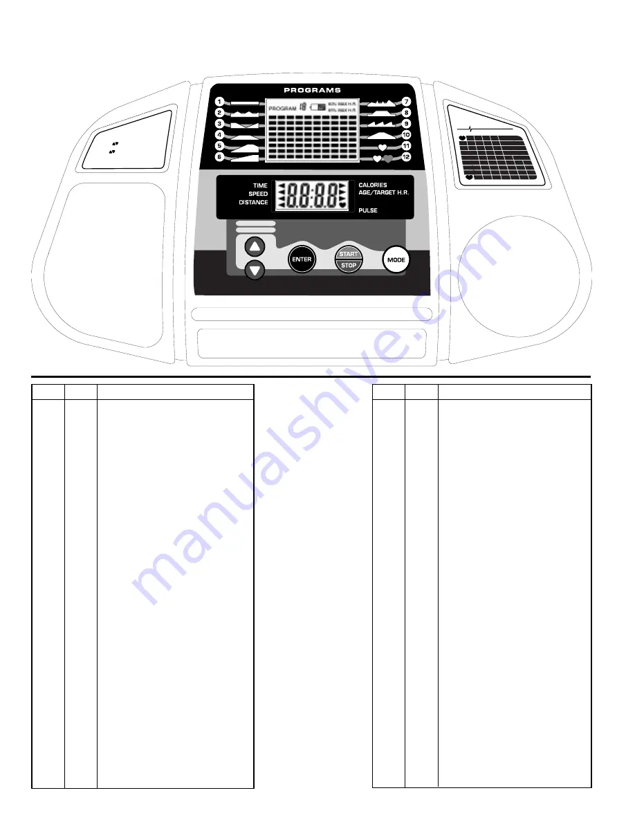
1. Press START/PAUSE for 2 seconds to 

    clear monitor.

2. Press          to select desired program.

     Press ENTER.

3. Press          to set desired time.

4. Enter AGE if program 11 or 12 was selected.

5. Press START and begin riding.

6. Press MODE while riding to select a function.

DIRECTIONS

BPM

Customer

Service:

800 - 321 - 9236

Heart Rate Training Zones

165

Age

20

30

40

50

60

70

80

Max Fat Burn

Fat Burn

Aerobic

118

105

110 115

95 103

90

145

125

120 130

115

125

110

125

130

140

138

145

155

Summary of Contents for 491

Page 1: ...to be free from all defects in material and workmanship when used according to the manufacturer s instructions See Limited Warranty Service for details If you have any comments or questions contact our Customer Service Department toll free at 1 800 321 9236 Monday through Friday 9 00 am to 5 00 pm Eastern Time Please record the following information and keep for reference Serial __________________...

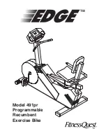
Page 2: ...Model 491pr Programmable Recumbent Exercise Bike TM ...

Page 3: ... and aerobic exercise tones and conditions the muscles we use every day to stand walk lift and turn It can actually transform our body composition by reducing body fat and increasing the proportion of lean muscle in our bodies Be sure to read through this Owner s Manual carefully It is the authoritative source of information about your Edge 491pr Recumbent Bike Retain this manual for future refere...

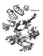
Page 4: ...4 24 6 2 4 24 59 60 61 67 5 4 59 60 6 64 62 71 70 66 65 68 51 7 3 8 FIGURE 10 11 14 15 10 34 43 36 35 50 7 9 24 22 69 1 4 5 21 28 27 4 23 24 4 26 33 25 18 30 19 20 20 56 57 58 4 31 28 31 4 55 46 54 49 48 53 48 47 16 32 27 28 31 63 16 15 17 14 72 4 49 24 29 38 37 37 ...

Page 5: ...1 62 63 64 65 66 67 68 69 70 71 72 73 QTY 1 1 1 1 2 8 1 1 1 1 2 2 1 6 1 1 1 1 1 1 1 2 2 1 1 1 1 1 1 2 2 1 3 2 1 1 PART NAME Reed Switch Console Tube Console Front Handlebar M8 x 60mm Machine Screw M6 x 1 x 10mm Machine Csrew Book Holder Center Cover Spring V Belt M10 Washer M10 Cap Nut Pulley M6 x 1 Nut Magnet Mag Brake Belt Tension Bracket M6 x 1 x 20mm Machine Screw M8 x 45mm Button Head Screw I...

Page 6: ... and should be under close supervision when using any exercise equipment 11 Use this machine only for its intended use as described in this manual Do not use attachments not recommended by the manufacturer 12 Only one person at a time should use this machine 13 Do not put hands feet or any foreign objects on or near this machine when in use by others 14 Always use this machine on a level surface 1...

Page 7: ...nformation 1 NAME MAILING ADDRESS AND TELEPHONE NUMBER 2 DATE OF PURCHASE 3 WHERE PRODUCT IS PURCHASED NAME OF RETAIL STORE CITY 4 MODEL NUMBER EXB01491 5 PART ORDER NUMBER AND DESCRIPTION All details depicted in this Owner s Manual and of the product itself are subject to change without notice Manual Packet contains Manual and Warranty Card Fastener Pack Hex Head Tool w Phillips Screw Driver 6mm ...

Page 8: ...rom 0 1 again AGE During the stop mode press the MODE key until the arrow points to the AGE function It will default at 25 STEP 1 Press the ENTER button to enter the AGE function Press the UP or DOWN button to input your age The digit will be flashing Press ENTER to go to another function or START to begin exercising SCAN User must manually scan through all functions once before computer starts sc...

Page 9: ...nt PROGRAM GRAPHICS 16 STEP 1 Press START STOP key 2 seconds to clear out previous program STEP 2 Press the UP or DOWN buttons to choose the desired Heart rate program program 11 or 12 STEP 3 Press ENTER for TIME mode Press the UP or DOWN buttons for the desired TIME setting STEP 4 Press ENTER for AGE mode Press the UP or DOWN buttons for the desired AGE setting STEP 5 You are now ready to begin e...

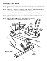
Page 10: ...ER 5 M8 x 1 25 CAP NUT 5 M8 x 1 25 CAP NUT 9 SUPPORT TUBE 8 REAR FOOT TUBE 3 FRAME 4 M8 WASHER FIGURE 2 Step 3 Remove the two M8 x 1 25 x 60 CAR RIAGE BOLTS 1 M8 WASHERS 4 and M8 x 1 25 CAP NUTS 5 from the REAR FOOT TUBE 8 Step 4 Insert two M8 x 1 25 x 60 CARRIAGE BOLTS 1 through square holes in REAR FOOT TUBE 8 FRAME 3 and SUPPORT TUBE 9 and fasten with M8 WASHERS 4 and M8 x 1 25 CAP NUTS 5 NOTE ...

Page 11: ...rt CARRIAGE TUBE 23 through SEAT CARRIAGE 19 and release LOCKING ARM This will hold CARRIAGE TUBE in place Step 7 Remove BUTTON HEAD SCREWS 24 and M8 WASHERS 4 from FRAME 3 Step 8 Slide CARRIAGE TUBE 23 over end of FRAME 3 and fasten with hardware removed in Step 7 Step 9 Attach CARRIAGE TUBE 23 to SUPPORT TUBE 9 with hardware removed in Step 5 Secure REAR FOOT TUBE NUTS now FIGURE 3 23 CARRIAGE T...

Page 12: ...START STOP button for over 2 seconds This will clear any other chosen function STEP 2 Next press the UP or DOWN buttons to scroll to the desired exercise program Then press ENTER The program will be displayed on the LCD window STEP 3 The TIME setting mode should now be displayed Press the UP or DOWN buttons to set the desired workout time STEP 4 Press the START button to begin exercising If you wa...

Page 13: ... counting at the programmed time setting Example If your time setting was 30 minutes and the computer has reached 0 00 the computer will stop tracking time after four seconds of inactivity and will continue once you resume exercising SPEED Displays your workout speed in miles per hour DISTANCE Displays the cumulative distance traveled during each workout up to a maximum of 99 9 miles The distance ...

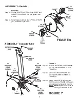
Page 14: ... and M6 WASHERS 28 Step 11 Attach BACK CUSHION 26 to one of four positions with PHILLIPS HEAD SCREWS 27 and M6 WASHERS 28 Select the proper position according to your height FIGURE 5 Step 12 Attach HANDLEBAR 29 to SEAT CARRIAGE 19 with BUTTON HEAD SCREWS 30 M8 WASH ERS 4 and M8 LOCKNUTS 31 31 M8 LOCKNUT 4 M8 WASHER 30 BUTTON HEAD SCREW 29 HANDLEBAR 19 SEAT CARRIAGE 27 PHILLIPS HEAD SCREW 28 M6 WAS...

Page 15: ... and M8 WASHERS 4 from FRAME 3 Step 16 Connect the PICKUP WIRE and EXTENSION WIRE to WIRES in FRAME 3 Step 17 Slide CONSOLE TUBE 39 over WIRES and into FRAME 3 Fasten with hardware removed in Step 15 NOTE DO NOT pinch wires while at taching CONSOLE TUBE 37 PEDAL STRAP PICKUP WIRE 4 M8 WASHER 3 FRAME 39 CONSOLE TUBE SHAFT 34 RIGHT PEDAL 4 M8 WASHER 24 BUTTON HEAD SCREW 24 BUTTON HEAD SCREW 24 BUTTO...

Page 16: ...rom a standing position balance yourself by holding onto a solid object or the wall Slowly squat down until the upper portion of your legs are level with your knees Return to the standing position WORKING OUT Too much two little how much is enough The key to a healthful program is defining your personal goals and establishing an exercise nutrition program that will help you to be successful At app...

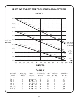
Page 17: ...0 100 195 165 136 190 161 133 185 157 129 180 153 129 175 148 129 170 144 119 165 140 115 160 136 112 155 131 108 150 127 105 145 123 101 140 119 98 AGE YRS TABLE 2 Exercise Warm Up THR Cool Down Total Sessions Total Time Week Period Minutes Period Time Per Wk Per Wk 1 2 4 60 65 8 5 17 3 51 3 4 5 65 70 10 5 20 3 60 5 6 5 70 75 15 5 25 3 75 7 8 5 70 80 20 5 30 3 90 9 10 5 70 85 25 5 35 3 105 11 12 ...

Page 18: ... CONSOLE TUBE Step 20 Attach FRONT HANDLEBAR 41 with PULSE GRIPS up to CONSOLE TUBE 39 with MACHINE SCREWS 42 M8 WASHERS 4 and M8 LOCKNUTS 31 NOTE DO NOT pinch wires between HANDLEBAR and CONSOLE TUBE Step 21 Carefully plug PICKUP WIRE EXTENSION WIRE and PULSE WIRES into bottom of CONSOLE 40 Step 22 Remove MACHINE SCREWS 43 from bottom of CONSOLE 40 and attach CON SOLE to CONSOLE TUBE 39 with MA C...

Page 19: ...ring of your heart rate with increased exercise demands Fluttering in your chest heart palpitations Stop exercising if you experience any of the following symptoms SET FITNESS GOALS General guidelines to follow If any of these symptoms occur call your doctor immediately If exercise is new to you don t push yourself too fast Be conscious of your body and what it is telling you If pain develops anyw...

Page 20: ... your pulse count the number of beats for 10 seconds Multiply the number of beats by six to determine your pulse rate per minute A chart is provided for you to log your heart rate at rest after warming up during your workout and two minutes during your cool down then 10 minutes after your cool down We recommend taking your heart rate at these times to accurately track your progress as it relates t...

Reviews: