background image

5

Spare Part list

NO.

Description

QTY

NO.

Description

QTY

1

Main Frame

1

11

Flat Washer

3

2

Rear Stabilizer

1

12

Seat

1

3

Front Stabilizer

1

13

Pedal(R)

1

4

Carriage Bolt

4

14

Fixing Bolt

4

5

Curved Washer

4

15

Front Post

1

6

Domed Nut

4

16

Monitor Hold

1

7

Pedal(L)

1

17

Monitor

1

8

Adjustment Knob

1

18

Fixing Bolt

2

9

Seat Post

1

19

Spring Washer

2

10

MS Lock Nut

3

20

Handlebar

1

PARTS LIST

SPARE PARTS PICTURE

Summary of Contents for TONERX TF-BB8001A

Page 1: ...ntain important information which will help you get the best from your equipment and ensure safe and correct assembly use and maintenance If you need help or have damaged or missing parts call the Cus...

Page 2: ...ty Information Parts List Exploded Diagram Assembly Instructions Step 1 Step 2 Step 3 Step 4 Step 5 Step 6 Step 7 Operating the Computer Exercise Instructions Declaration 03 4 05 06 07 07 07 08 08 09...

Page 3: ...program you should consult your doctor to determine if you have any physical or health conditions that could create a risk to your health and safety or prevent you from using the equipment properly Yo...

Page 4: ...ent until the problem has been rectified 9 Wear suitable clothing whilst using the equipment Avoid wearing loose clothing which may get caught in the equipment or that may restrict or prevent movement...

Page 5: ...1 12 Seat 1 3 Front Stabilizer 1 13 Pedal R 1 4 Carriage Bolt 4 14 Fixing Bolt 4 5 Curved Washer 4 15 Front Post 1 6 Domed Nut 4 16 Monitor Hold 1 7 Pedal L 1 17 Monitor 1 8 Adjustment Knob 1 18 Fixi...

Page 6: ...6 EXPLODED DIAGRAM...

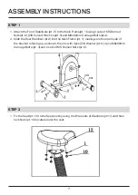
Page 7: ...Bolts pt 4 2 Slide the Rear Stabilizer pt 2 into the Main Frame pt 1 making sure the open side of the bracket is facing up as shown then fix with 4pcs Zl 8 Washer pt 5 2pcs M8x60mm Carriage Bolts pt...

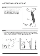
Page 8: ...en the bike is fully assembled Secure the seat in position with the Adjustment Knob pt 8 STEP 4 1 Take the Front Post lS and connect the Upper Monitor Wire with Lower Monitor Wire See picture A B C Th...

Page 9: ...itor Holder pt 16 Fix Handlebar pt 20 on the Front by 2 pcs M8 30mm fixing Bolt pt 18 and Spring Washers pt 19 STEP 6 1 Fix the L pedal pt 7 on the main frame by wrench 13 15 in counter clockwise Fix...

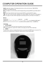
Page 10: ...ey until brand TMR appear o CAL The calories burned will be displayed by pressing mode key until brand cal appear o Manual TIM E TMR 00 00 99 59 MIN SPEED SPD 0 0 99 9KM H DISTANCE DST 0 00 999 9KM CA...

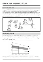
Page 11: ...a few stretching exercises as shown below Each stretch should be held for approximately 30 seconds do not force or jerk your muscles into a stretch if it hurts STOP THE EXERCISE PHASE This is the sta...

Page 12: ...will put more strain on your leg muscles and may mean you cannot train for as long as you would like If you are also trying to improve your fitness you need to alter your training program You should...

Page 13: ...with EN ISO 20957 5 2016 Stationary training equipment Part 5 Stationary exercise bicycles and upper body crank training equipment additional specific safety requirements and test methods Authorised S...

Page 14: ...14...

Reviews: