


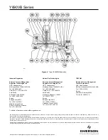
Y690VB Series
3
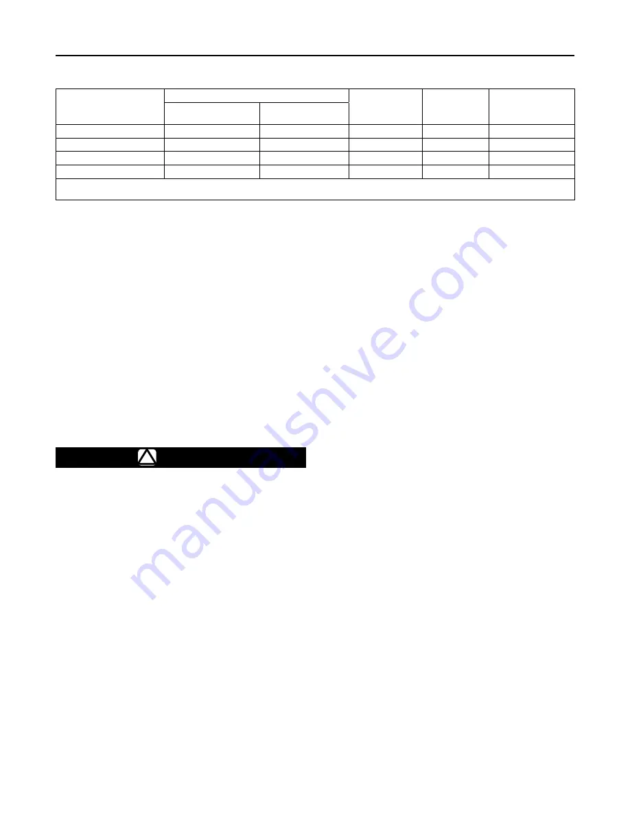
Table 1. Vacuum Pressure Information
VACUUM CONTROL
PRESSURE RANGE
(1)(2)
CHANGE IN VACUUM TO WIDE-OPEN
Spring
PART NUMBER
SPRING COLOR
Spring WirE
DIAMETER
1/4-inch (6,4 mm) Orifice
1/2-inch (13 mm)
Orifice
0 to 4-inches w.c. (0 to 10 mbar) 0.6-inches w.c. (1,5 mbar)
1.3-inches w.c. (3 mbar)
0N039427222
Unpainted
0.062-inches (1,6 mm)
0 to 1.0 psig (0 to 0,07 bar)
10-inches w.c. (25 mbar)
0.7 psig (0,05 bar)
0N086127022
Unpainted
0.125-inches (3,2 mm)
0 to 2.1 psig (0 to 0,14 bar)
1.2 psig (0,08 bar)
2.4 psig (0,17 bar)
0N004327022
Yellow
0.172-inches (4,4 mm)
0 to 5 psig (0 to 0,34 bar)
3.2 psig (0,22 bar)
6.3 psig (0,43 bar)
1D141827012
Dark blue
0.207-inches (5,3 mm)
1. Spring ranges based on atmospheric inlet pressure.
2. To convert to inches Hg, multiply psig value by 2.04.
Note
If this equipment is shipped mounted on
another unit, install that unit according
to the appropriate instruction manual.
1. Only personnel qualified through training and
experience should install, operate, and maintain
this equipment. For Y690VB Series equipment
that is shipped separately, make sure that there is
no damage to or foreign material in it. Also ensure
that all tubing and piping have been blown free.
2. This equipment may be installed in any position
as long as the flow through the body is in the
direction indicated by the arrow attached to the
body. If continuous operation is required during
inspection or maintenance, install a three-way
bypass valve around the equipment.
Warning
!
This equipment may vent some gas
to the atmosphere. In hazardous or
flammable gas service, vented gas may
accumulate and cause personal injury,
death, or property damage due to fire or
explosion. Vent equipment in hazardous
gas service to a remote, safe location
away from air intakes or any hazardous
area. The vent line or stack opening
must be protected against condensation
or clogging.
Principle of Operation
The Y690VB Series vacuum breakers (Figure 2) are
used in applications where an increase in vacuum
must be limited. An increase in vacuum (decrease
in absolute pressure) is transmitted to the lower side
of the diaphragm, opening the disk assembly. This
permits positive pressure, atmosphere, or an upstream
vacuum that has higher absolute pressure than the
downstream vacuum, to enter the system and restore
the controlled vacuum to its original pressure setting.
A Type Y690VB (Figure 3) direct-operated vacuum
breaker is self-contained and requires no control
line. A Type Y690VBM (Figure 4) vacuum breaker
requires a control line from the 1/2 NPT tapping in
the diaphragm case assembly to the point where the
vacuum needs to be controlled.
Startup and Adjustment
All Y690VB Series equipment can be placed in
operation by slowly introducing inlet vacuum or
pressure. This equipment takes control when vacuum
is established. This equipment is suitable for the
pressure range stamped on the nameplate (key 46),
and listed in Table 1. To adjust the pressure setting,
remove the closing cap (key 22) and turn the adjusting
nut (key 20) clockwise to increase the pressure setting
or counterclockwise to decrease the setting. Replace
the cap after making this adjustment. If desired, the
closing cap may be wired to the hole provided in the
spring case (key 3) to discourage tampering.
Shutdown
First close the nearest upstream shutoff valve and then
close the nearest downstream shutoff valve to vent
the equipment properly. Next, open the vent valve
between the equipment and the downstream shutoff
valve nearest to it. All pressure between these shutoff
valves is released through the open vent valve.
Maintenance
Equipment parts are subject to normal wear and
must be inspected and replaced as necessary. The
frequency of inspection and replacement of parts
depends on the severity of service conditions and
upon applicable codes and government regulations.