


Instruction Manual
D104296X012
LCP200 Local Control Panel
August 2018
7
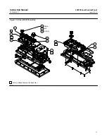
Figure 3. Fisher LCP200 with Mounting Bracket
Electrical Connections
WARNING
Select wiring and/or cable glands that are rated for the environment of use (such as hazardous location, ingress protection,
and temperature). Failure to use properly rated wiring and/or cable glands can result in personal injury or property damage
from fire or explosion.
Wiring connections must be in accordance with local, regional, and national codes for any given hazardous area approval.
Failure to follow the local, regional, and national codes could result in personal injury or property damage from fire or
explosion.
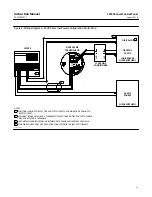
Refer to the appropriate wiring diagram, as defined in table 3, based on your installation requirements. Also refer to
figure 5 for LCP200 terminal connections, label details and information, as well as DVC6200 SIS terminal box details.
When connecting the wiring terminals tighten to a torque of 0.8 N•m (7 lbf•in) +/- 10%, using a 3 mm thin blade, flat
head screwdriver.
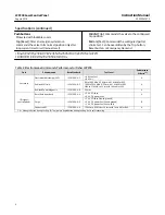
Table 3. Wiring Configurations with DVC6200 SIS Digital Valve Controller
LCP200 Power Source
System Output
DVC6200 SIS Mode (Current or Voltage)
Refer to figure
LOOP
8-20 mA
Point-to-Point
24 VDC
Multi-Drop
24 VDC External Power
4-20 mA
Point-to-Point
24 VDC
Multi-Drop