


Designs D & DA
4
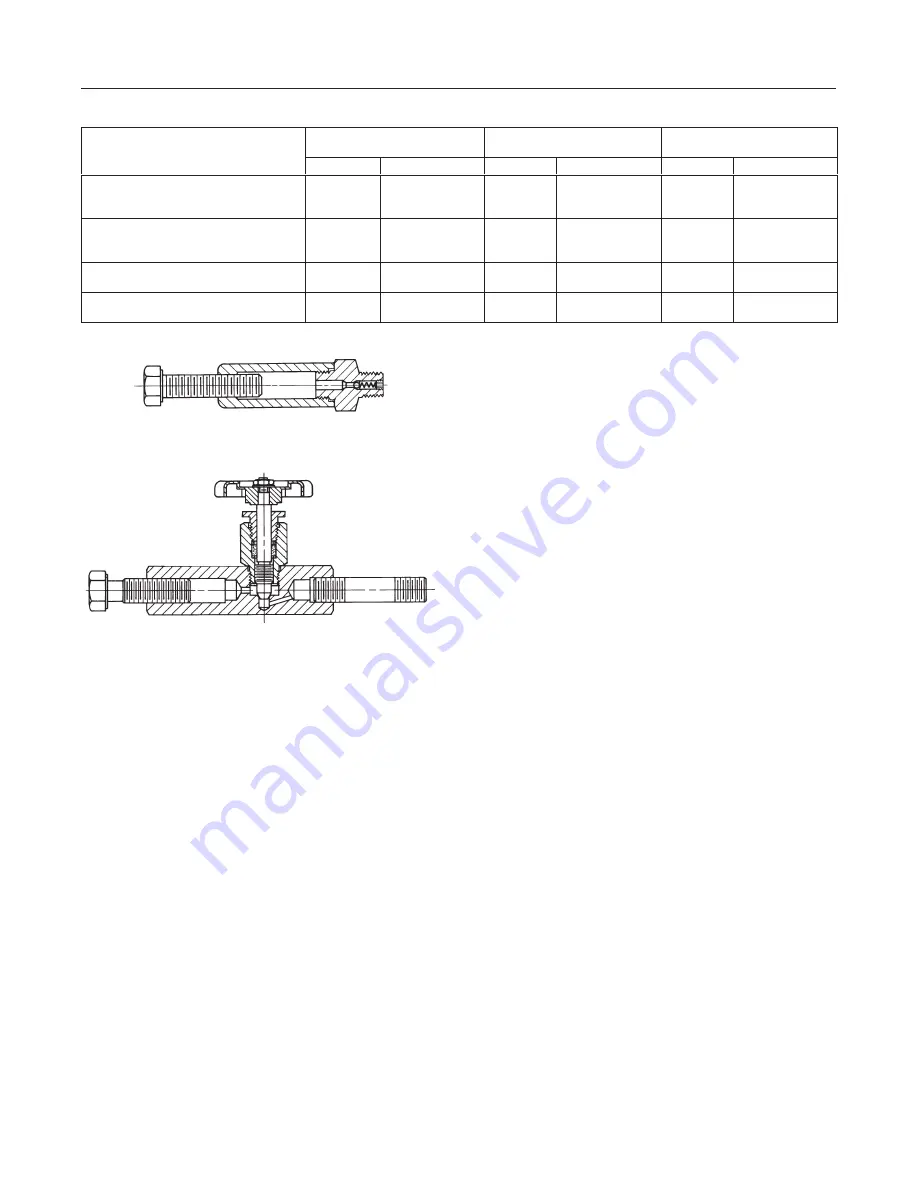
Table 3. Bolting Torque for Packing Box Nuts (Key 15)
VALVE
RATING
STEM
DIAMETER
MINIMUM
RECOMMENDED TORQUE
MAXIMUM
RECOMMENDED TORQUE
RATING
Inches
mm
Lbf
S
in
N
S
m
Lbf
S
in
N
S
m
3600 or to ANSI Class 1500
3/8
1/2
3/4
9.5
12.7
19.1
36
66
144
4
7
16
48
96
216
5
11
24
6000 or ANSI Class 2500
3/8
1/2
3/4
9.5
2.7
19.1
42
78
180
5
9
20
60
108
264
7
12
30
9000 psi
1/2
3/4
12.7
19.1
54
180
6
20
72
264
8
30
10,000 psi
1/2
3/4
12.7
19.1
54
180
6
20
72
264
8
30
Figure 2. Lubricator and Lubricator/Isolating Valve (optional)
10A9421-A
AJ5428-D
A0832-2/IL
Because of the care Fisher Controls takes in meeting
all manufacturing requirements (heat treating, dimen-
sional tolerances, etc.), use only replacement parts
manufactured or furnished by Fisher Controls.
Note
Whenever a gasket seal is disturbed by
removing or shifting gasketed parts,
install a new gasket upon reassembly.
This is necessary to ensure a good gas-
ket seal because the used gasket might
not seal properly.
Packing Lubrication
The valve might have an optional lubricator or lubrica-
tor/isolating valve (figure 2) in the tapped bonnet. Use
the lubricator or lubricator/isolating valve for PTFE/
composition or other packings that need lubrication.
Use a silicon-base lubricant. Do not lubricate packing
used in oxygen service. To operate the lubricator, turn
the cap screw clockwise to force the lubricant into the
packing box. The lubricator/isolating valve operates
the same way except open the isolating valve before
turning the cap screw. Close the isolating valve after
lubrication is completed.
Packing Maintenance
Refer to figures 3, 4, and 5 for key number locations.
For spring-loaded single PTFE V-ring packing, the
packing spring (key 9) maintains a sealing force on the
packing. If you find leakage around the packing follow-
er (key 10), check to be sure the packing follower is
touching the bonnet (key 5). If the packing follower is
not touching the bonnet, tighten the packing flange
nuts (key 15) until the packing follower touches the
bonnet. If you cannot stop leakage in this way, pro-
ceed to the
Replacing Packing procedure.
If there is unwanted packing leakage with other than
spring-loaded packing, first try to limit the leakage and
seal the stem. To limit the leakage, tighten the packing
flange nuts (key 15) to at least the minimum recom-
mended torque in table 3. However, do not exceed the
maximum recommended torque in table 3, or exces-
sive friction might result. If the packing (key 8) is rela-
tively new and tight on the stem, and tightening the
packing flange nuts does not stop the leakage, a worn
or nicked valve stem might prevent a seal. If the leak-
age comes from the outside diameter of the packing,
nicks or scratches around the packing box wall might
cause the leakage. While replacing the packing per
the numbered steps below, inspect the valve stem and
packing box wall for nicks and scratches.
Replacing Packing
Except where indicated, refer to figures 3, 4, and 5 for
key number locations.
1. Isolate the control valve from the line pressure, re-
lease pressure from both sides of the valve body, and
drain the process media from both sides of the valve.
If using a power actuator, also shut-off all pressure
lines to the power actuator and any leak-off piping
Summary of Contents for D Series
Page 11: ...Designs D DA 11 ...