Instruction Manual
D101640X012
CV500 Valve
June 2017
26
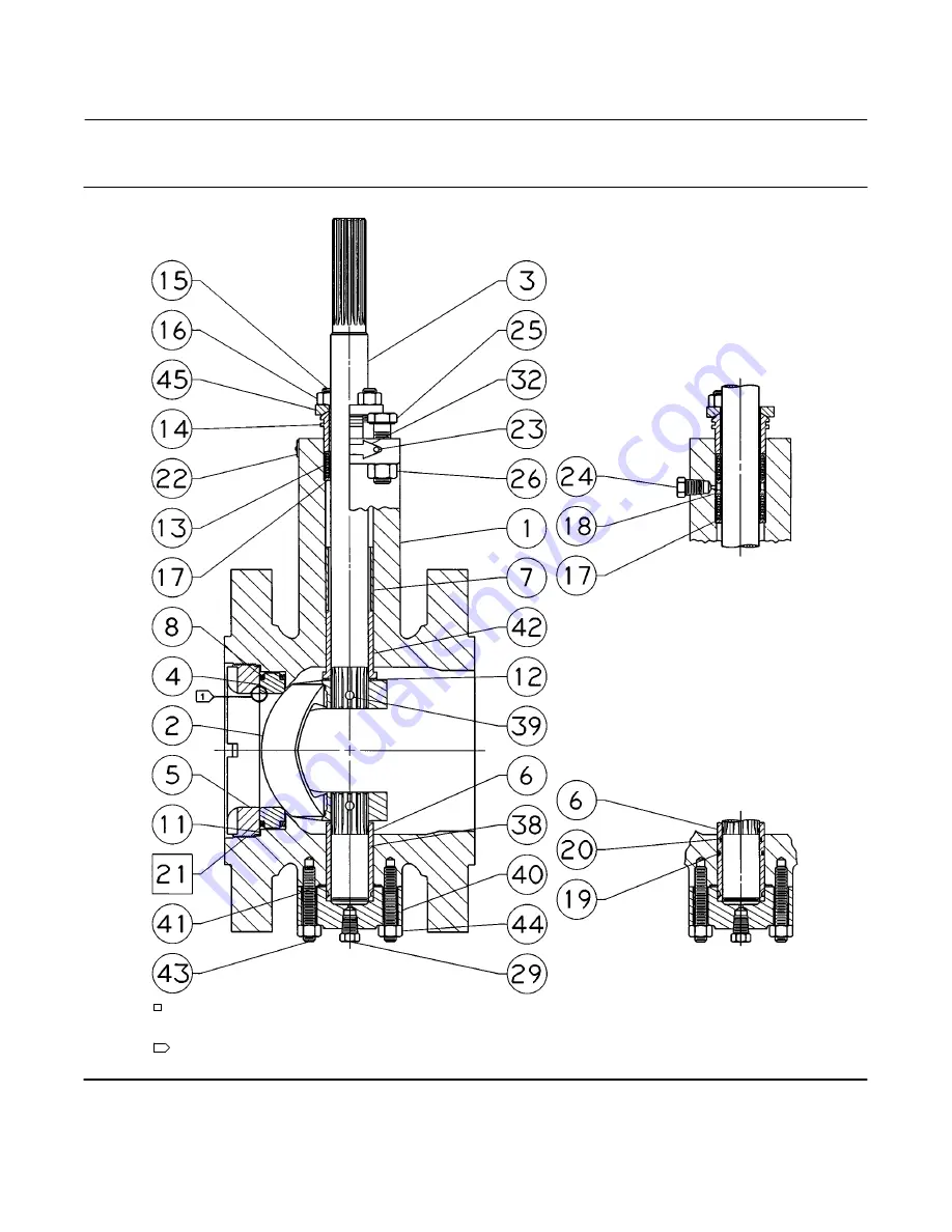
Figure 10. Fisher CV500 Valve, NPS 10 and 12
42B5286‐A
NOTE: MEASURE GAP HERE
1
KEY NUMBERS NOT SHOWN ARE 28, 30, 31, 33, 36, 37, 130, AND 131
DOUBLE
PACKING
SEALED
BEARING
APPLY LUB
Page 1: ...efer to separate manuals for information concerning the actuator and accessories Description The CV500 Cam Vee Ball rotary control valve has a Vee Ball style segmented ball in a valve body similar to the V500 valve The CV500 is a flanged valve figure 1 with a self centering seat eccentrically rotating V notch ball and splined valve shaft Suitable for forward or reverse flow use this valve mates wi...
Page 2: ...tion depends on the desired open valve position and flow direction required by operating conditions Valve Ball Rotation Counterclockwise to close when viewed from actuator side of valve body through 90 degrees of ball rotation Valve Body Actuator Action With diaphragm or piston rotary actuator field reversible between J push down to close extending actuator rod closes valve body and J push down to...
Page 3: ... 200 600 600 600 350 450 500 200 to 300 600 600 600 350 5 450 500 335 6 300 to 400 600 600 600 345 5 450 500 320 6 400 to 500 2 600 600 600 340 5 450 500 315 6 1 29_C 20_F for WCC steel valve body material 2 For hot water or steam service limit maximum temperature to 260_C 500_F 3 The pressure or temperature limits in this table or in any applicable code limitation should not be exceeded 4 Standar...
Page 4: ... 1 1 2 75 217 298 10 1 3 4 1 3 4 458 12 2 1 8 2 1 8 558 2 1 8 2 1 Spline diameter that connects to actuator versus shaft diameter Key numbers are shown in figure 9 for NPS 3 through 8 and in figure 10 for NPS 10 and 12 1 If the valve body key 1 is to be stored before installation protect the flange mating surfaces and keep the valve body cavity dry and clear of foreign material 2 Install a three v...
Page 5: ...TUATOR POSITION ACTUATOR MOUNTING STYLE VALVE OPEN 1 2 3 4 NOTES 1 ARROW ON LEVER INDICATES DIRECTION OF ACTUATOR THRUST TO CLOSE VALVE 2 PDTC PUSH DOWN TO CLOSE PDTO PUSH DOWN TO OPEN 3 F FORWARD FLOW R REVERSE FLOW RIGHT HAND STYLE A PDTC STYLE B PDTO STYLE C PDTO STYLE D PDTC LEFT HAND F R F R F R F R C0741 ...
Page 6: ... 2 5 60 73 PN63 4 M24 x 3 70 85 PN100 4 M27 x 3 80 97 Valve Size NPS CL Qty Bolt Size Bolt Length Inch Overall Length Inch 3 150 300 4 3 4 10 UNC 2 38 2 88 600 4 3 4 10 UNC 2 38 2 88 4 150 4 5 8 11 UNC 2 00 2 44 300 4 3 4 10 UNC 2 38 2 88 600 4 7 8 9 UNC 2 75 3 38 Line Studs Key 36 1 Valve Size NPS R PN Qty Bolt Size Bolt Length mm 6 PN10 and 16 6 M20 x 2 5 110 PN25 and 40 6 M24 x 3 125 8 PN10 4 M...
Page 7: ...phere or where the process fluid is combustible electrically bond the drive shaft key 3 to the valve according to the following step Note Standard CV500 packings key 13 are composed either entirely of conductive packing rings graphite ribbon packing or partially of conductive packing rings a carbon filled PTFE female adaptor with PTFE V ring packing or a graphited composition packing ring with PTF...
Page 8: ...re Relieve process pressure on both sides of the valve Drain the process media from both sides of the valve D Vent the power actuator loading pressure and relieve any actuator spring precompression D Use lock out procedures to be sure that the above measures stay in effect while you work on the equipment D Always wear protective gloves clothing and eyewear when performing any maintenance operation...
Page 9: ...used 18 need to be replaced WARNING Refer to the WARNING at the beginning of the Maintenance section in this instruction manual 1 Isolate the control valve from the line pressure release pressure from both sides of the valve body and drain the process media from both sides of the valve If using a power actuator also shut off all pressure lines to the power actuator release all pressure from the ac...
Page 10: ...age and retighten the packing nuts as necessary Replacing Retainer Seat Ring and Face Seals This procedure is to be performed if the control valve is not shutting off properly if installing a different seat ring or if seat ring inspection is necessary The actuator and valve must be removed from the pipeline however the actuator may remain mounted during this procedure Key numbers refer to figure 9...
Page 11: ...ONLY INCLUDED IN PTFE V RING PACKING SET KEY 13 FOR ONLY PTFE BOUND COMPOSITION PACKING TOP RING IS CONDUCTIVE GRAPHITE FILAMENT RING 1 2 3 ZINC WASHERS KEY 28 ZINC WASHERS KEY 28 ZINC WASHERS KEY 28 PACKING RING KEY 13 PACKING RINGS KEY 13 PACKING RINGS KEY 13 PACKING RINGS PACKING RINGS PACKING BOX RING KEY 17 PACKING BOX RING KEY 17 PACKING BOX RING KEY 17 PACKING BOX RING KEY 17 PACKING BOX RI...
Page 12: ...NTERN RING KEY 110 LANTERN RING KEY 110 PACKING BOX RING KEY 107 PACKING BOX RING KEY 107 PACKING BOX RING KEY 107 PACKING BOX RING KEY 107 PACKING BOX RING KEY 107 GRAPHITE PACKING SET KEY 105 PACKING RING KEY 108 PACKING FLANGE STUD KEY 100 PACKING FLANGE NUT KEY 101 PACKING FLANGE KEY 102 SPRING PACK ASSEMBLY KEY 103 PTFE PACKING SET KEY 105 1 Isolate the control valve from the line pressure re...
Page 13: ...and do not require replacement continue to the Assembly procedure in this manual Assembly WARNING Seat ring installation requires that the ball key 2 remain in the open position The ball closes with a shearing cutting motion which could result in personal injury To avoid personal injury or damage to tools valve parts or other items resulting from the ball closing prevent against ball travel by usi...
Page 14: ...11 2 63 5 11 2 25 4 6 12 1 50 44 2 50 44 1 00 8 203 2 50 8 11 2 101 6 11 2 38 1 8 00 2 00 44 4 00 44 1 50 10 241 3 50 8 11 2 127 0 19 1 38 1 9 5 2 00 44 5 00 75 1 50 12 273 0 50 8 11 2 127 0 25 4 38 1 10 75 2 00 44 5 00 1 00 1 50 Table 6 Data for Making and Using the Retainer Tool VALVE SIZE NPS RETAINER TORQUE NSm LbfSft 3 515 380 4 1170 860 6 2305 1700 8 3120 2300 10 4750 3500 12 6100 4500 Figur...
Page 15: ...if necessary until the clearance is within maximum and minimum values D If the measured clearance is smaller than the minimum remove the retainer seat ring and face seals clean the parts and reassemble so as to obtain the necessary minimum clearance 10 Perform the Adjusting Actuator Travel procedure in this manual and then install the control valve in the pipeline Replacing Ball Shaft and Bearings...
Page 16: ...e shaft is removed Table 7 Data for Tapped Holes on Valve Shaft VALVE SIZE NPS SHAFT DIAMETER THREAD SIZE UNC Through Valve At Spline End Through Valve At Spline End mm Inches 3 25 4 25 4 1 00 1 00 3 8 16 25 4 19 1 1 00 0 75 5 16 18 4 31 8 31 8 1 25 1 25 3 8 16 6 38 1 38 1 1 50 1 50 1 2 13 38 1 31 8 1 50 1 25 3 8 16 8 38 1 38 1 1 50 1 50 1 2 13 10 44 5 44 5 1 75 1 75 1 2 13 12 53 8 53 8 2 12 2 12 ...
Page 17: ...ure 6 Taper and Expansion Pin Removal from Ball and Drive Shaft E0575 DRIVE PINS OUT FROM THIS END SMALLER HOLE SLASH MARK ON SPLINED END OF SHAFT Note For NPS 3 through 8 two shaft bearings key 6 are located inside the valve body on either side of the ball Only one of these two bearings is identified by key 6 The other bearing is located along the drive shaft on the other side of the V notch ball...
Page 18: ... figure 7 Press the bearing into the valve body cavity 16 If used remove the O rings keys 19 and 20 from the bearings Also for NPS 3 through 8 remove the pipe plug key 29 Assembly Note Before starting to assemble the valve components place the valve body key 1 on a flat surface with the retainer key 5 facing down as shown in figure 8 This orientation of the valve allows easier installation of the ...
Page 19: ...follower shaft is flush with the outside edge of the ear Place the ball in the valve body cavity with the ear containing the follower shaft adjacent to the follower shaft bore Slide the follower shaft through the ear of the ball and into the bearing key 6 which was previously installed in step 3 For NPS 6 and 8 locate the smaller diameter hole in the V notch ball ear Place the ball in the valve bo...
Page 20: ...cal and facing out from the center of the shaft in the same direction as the ball seating surface See figure 8 Figure 8 Taper and Expansion Pin Insertion into Ball and Drive Shaft E0576 PINS GO IN FROM THIS END LARGER HOLE SLASH MARK ON SPLINED END OF SHAFT BENCH Note When the valve drive shaft is correctly positioned for NPS 3 through 8 the slash mark on the splined end will be parallel with the ...
Page 21: ...idges Make certain the holes in the ear of the ball will align with the hole in the drive shaft Secure the ball to the drive shaft by using pin punches and driving in the groove pin until it is flush with the surface of the ball ear Make certain that the groove pin goes completely through the drive shaft and into the opposite side of the ball ear 13 Rotate the ball by hand to check that it rotates...
Page 22: ...nting style and position and to orient the actuator lever with the valve drive shaft key 3 2 For actuators with clamped levers pull the drive shaft key 3 by hand toward the packing key 13 so that the ball key 2 and thrust washer key 12 are tight against the bearing closest to the packing key 6 for NPS 3 through 8 and key 42 for NPS 10 and 12 Clamp the lever to the valve drive shaft CAUTION Do not ...
Page 23: ...ned to each valve body and stamped on the nameplate Always refer to this serial number when corresponding with your Emerson sales office or Local Business Partner regarding spare parts or technical information WARNING Use only genuine Fisher replacement parts Components that are not supplied by Emerson Automation Solutions should not under any circumstances be used in any Fisher valve because they...
Page 24: ... 2 102 Packing Flange Packing Flange 1 1 103 Spring Pack Assembly Spring Pack Assembly 1 1 105 Packing Set Packing Set 1 1 106 Anti Extrusion Washer Anti Extrusion Washer 2 107 Packing Box Ring Packing Box Ring 1 1 Repair Kits for ENVIRO SEAL Packing Packing boxes in these valves may be deep drilled If the valve body being repaired has a deep packing box additional parts are required Refer to the ...
Page 25: ... D101640X012 CV500 Valve June 2017 25 Figure 9 Fisher CV500 Valve NPS 3 Through 8 42B3374 A TCM SEAL DOUBLE PACKING SEALED BEARING NOTE MEASURE GAP HERE 1 KEY NUMBERS NOT SHOWN ARE 28 30 31 33 36 37 130 AND 131 APPLY LUB ...
Page 26: ...anual D101640X012 CV500 Valve June 2017 26 Figure 10 Fisher CV500 Valve NPS 10 and 12 42B5286 A NOTE MEASURE GAP HERE 1 KEY NUMBERS NOT SHOWN ARE 28 30 31 33 36 37 130 AND 131 DOUBLE PACKING SEALED BEARING APPLY LUB ...
Page 27: ...INGS SINGLE PTFE PACKING STANDARD DEPTH BOX DOUBLE PTFE PACKING STANDARD DEPTH PACKING BOX DOUBLE PTFE PACKING WITH LEAKOFF OPTIONAL DEEP PACKING BOX 14B0095 A 42B8445 B 42B8445 B 42B8445 B Figure 12 Typical ENVIRO SEAL Rotary Packing Arrangements with Graphite Packing STACKING ORDER OF GRAPHITE PACKING RINGS GRAPHITE PACKING STANDARD DEPTH BOX 14B0086 A 42B8445 B NOTES APPLY LUBRICANT THESE TWO S...
Page 28: ...lange Stud 101 Packing Flange Nut 102 Packing Flange 103 Spring Pack Assembly 105 Packing Set 106 Anti Extrusion Ring Composition graphite 107 Packing Box Ring 108 Packing Ring 109 Anti Extrusion Ring 110 Lantern Ring 111 Tag 112 Cable Tie 113 Lubricant Recommended spare parts Emerson Automation Solutions Marshalltown Iowa 50158 USA Sorocaba 18087 Brazil Cernay 68700 France Dubai United Arab Emira...