Fisher A31A Instruction Manuals Download Page 11

Model A31A

11

Table 6. Torque Values for Fasteners

FASTENER NOMINAL SIZE

#10

1/4

5/16

3/8

7/16

1/2

9/16

5/8

3/4

7/8

1

1-1/8

Retaining

Pounds-inch

Pounds-Foot

Retaining

Ring

41

100

220

400

53

83

119

166

296

480

720

1000

Ring

Screws

Newton

S

meters

4.6

11

25

45

72

112

161

225

401

651

976

1356

G

Pounds-inch

Pounds-Foot

Gasket

Retaining

35

81

167

295

39

59

86

119

210

330

480

617

Retaining

Bolts

Newton

S

meters

Bolts

4.0

9.2

19

33

53

80

117

161

286

447

651

837

Nore: These values are based upon standard materials, S66286/Inconel screws and ASTM A193GRB6 bolts. For other special fasterer materials, please contact your Fisher Controls
sales office or sales representative.

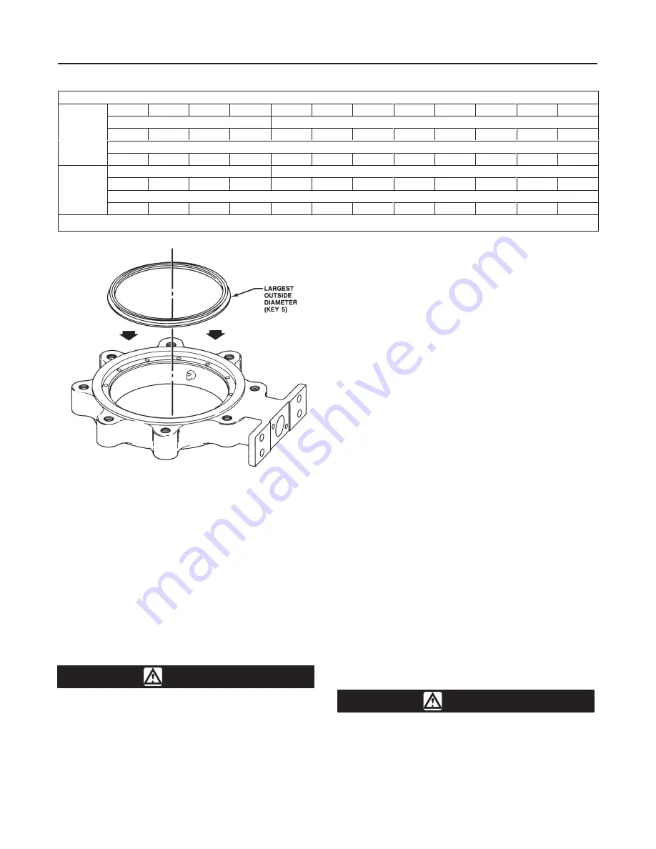
Figure 8. Typical Seal Installation

A5251-1*/IL

Removing the Valve

1.  Disconnect any operating lines providing air pres-
sure, electric power, or a control signal to the actuator.
Be sure the actuator cannot suddenly open the valve.
Vent the power actuator loading pressure.

2.  Use bypass valves or completely shut off the pro-
cess to isolate the valve from process pressure. Re-
lieve process pressure on both sides of the valve.
Drain the process media from either side of the valve.

CAUTION

Damage to the valve disk can occur if
the disk is not closed when the valve is
being removed from the pipeline. If nec-
essary, stroke the actuator to place the
disk in the closed position while remov-
ing the valve from the pipeline.

3.  Loosen the flange bolting that holds the valve.
Make sure the valve cannot slip or twist while loosen-
ing and removing the bolting.

4.  Before removing the valve from the pipeline, make
sure the valve disk is closed. Removing the valve with
the disk open could cause damage to the disk, piping,
or pipe flanges.

5.  After removing the valve from the pipeline, move
the valve to an appropriate work area. Always support
the valve properly.

6.  When valve maintenance is complete, refer to the
Installation procedures in this manual.

Seal Maintenance

Note

For larger valves, it is possible to re-
place the seal (key 5) while the actuator
is mounted to the valve and can be ac-
complished by cycling the valve to 90
degrees open.

Key numbers in this procedure are shown in figure 9
unless otherwise indicated.

1.  After removing the valve from the pipeline, remove
the manual or power actuator. Manually rotate the up-
per shaft (key 3) counterclockwise until the disk has
moved a full 180 degrees away from the closed posi-
tion.

WARNING

Avoid personal injury or property dam-
age caused by the impact of a falling or
tipping of a large valve. Support large
valves during maintenance.

Summary of Contents for A31A

Page 1: ...odel A31A High Per formance Butterfly Valve see figure 1 Refer to sep Figure 1 Typical Model A31A Valves W5812 1 IL W5811 1 IL arate instruction manuals for information covering the actuator and accessories Only personnel qualified through training or experience should install operate and maintain this control valve If you have any questions concerning these instruc tions contact your Fisher Contr...

Page 2: ...rols Catalogs 10 and 12 Flow Coefficient Ratio 2 100 to 1 Noise Levels See Fisher Controls Catalogs 10 or 12 for sound pressure level prediction Valve In Line Position Shaft horizontal See figure 4 Valve Actuator Action With diaphragm or piston rotary actuator field re versible between J push down to close extending actuator rod closes valve and J push down to open extending actuator rod opens val...

Page 3: ...Model A31A 3 Figure 2 Maximum Pressure Temperature Ratings B2335 2 IL ...

Page 4: ... to 300 65 to 300 80 to 400 40 to 450 40 to 149 54 to 149 62 to 204 40 to 232 Seal Ring NOVEX S31600 Seal 3 Ring Class 150 NOVEX S31600 Seal 3 Ring Class 300 NOVEX S21800 Seal Ring Class 300 20 to 1000 20 to 1500 20 to 1500 29 to 538 29 to 816 29 to 816 Seal Ring Cryogenic Seal Ring Contact your Fisher Controls sales representative or sales office 1 NACE trim constructions are available consult yo...

Page 5: ...flanges or pipe mating with valves are shown in tables 3 and 4 Valve Orientation The valve can be installed in any orientation however it is recommended that the valve drive shaft be hori zontal and the actuator vertical as shown in figure 4 Install the valve with the high pressure shutoff side in the direction noted by the flow arrow for proper instal lation and see figure 4 for more information ...

Page 6: ... the minimum pipe or flange I D required for disk swing clearance Table 4 Valve Body Data Wafer Style Valves Class 300 VALVE SIZE INCHES SHAFT DIA AT YOKE BEARING FACE TO FACE DIMENSI ON 1 MINI MUM I D 2 APPROX WEIGHT POUNDS INCHES Inches Wafer Single Flange 14 1 3 4 4 5 8 11 98 276 510 16 1 3 4 5 1 4 13 63 417 663 18 2 1 4 5 7 8 15 32 524 907 20 2 3 4 6 1 8 17 40 817 1215 24 2 3 4 7 1 8 20 59 105...

Page 7: ...ting lengths shown by 1 4 inch Figure 4 Proper Installation Steps B2263 1 IL Adjusting the Actuator Travel Stops or Travel Key number locations are shown in figure 9 unless otherwise noted 1 Refer to the actuator instruction manual to locate the actuator travel stop that control the closed position of the valve disk key 2 When adjusting the travel stop or travel make sure that the disk is from 0 t...

Page 8: ...al torque value tighten each flange bolt again to allow for gasket compression Packing Adjustment and Shaft Bonding WARNING Personal injury could result from pack ing leakage Valve packing was tight ened before shipment however the packing might require some readjust ment to meet specific service condi tions 1 For PTFE or graphite packing Tighten standard packing follower nuts only enough to preve...

Page 9: ...tuator instruction manual for actuator removal and replacement procedures The actuator stops or travel stops must limit the rotation of the valve shaft See the CAUTION below CAUTION When using an actuator the actuator travel stop or actuator travel stop for actuators without adjustable stops must be adjusted so the disk stop in the valve does not absorb the output of the actuator Failure to limit ...

Page 10: ... extractor to remove packing Insert the corkscrew like end of the tool into the first piece of packing and pull firmly to remove the packing Repeat this process until all packing parts have been re moved CAUTION Be careful when cleaning the packing box Scratches to the upper shaft key 3 or inside diameter of packing bore might cause leakage 4 Before installing new packing clean the packing box 5 I...

Page 11: ...ve disk can occur if the disk is not closed when the valve is being removed from the pipeline If nec essary stroke the actuator to place the disk in the closed position while remov ing the valve from the pipeline 3 Loosen the flange bolting that holds the valve Make sure the valve cannot slip or twist while loosen ing and removing the bolting 4 Before removing the valve from the pipeline make sure...

Page 12: ...ou have a maintenance kit use the seal installation tools 3 Carefully tuck the O ring downward into the body T slot until the seal ring is completely entrapped in the body T slot and it completely covers the backup O ring 4 Re install the retaining ring and the socket head cap screws Tighten the cap screws just enough to eliminate any movement of the retaining ring Do not over tighten the retainin...

Page 13: ...ve disk is not in contact with the valve internal travel stop see figure 5 The valve disk should be positioned from 0 to 0 030 inch 0 to 0 76 mm away from the inter nal stop in the valve body see figure 5 9 Use an appropriate tool such as a feeler gauge to position the disk key 2 from 0 to 0 030 inch 0 to 0 76 mm away from the internal stop in the valve body This adjustment is necessary to be cert...

Page 14: ...inside thread of the pins The rod should ex tend several inches above the disk when it is screwed into a pin d After screwing the rod into the pin slide the spacer over the rod and pin Thread a nut onto the rod and tighten it As you tighten the nut the nut will drive the spacer against the disk The increas ing force will draw the pin from the disk 6 The gasket retainer keys 19 and 20 figure 9 on t...

Page 15: ...packing box Push the drive shaft throught the bearing Hold the drive shaft drive bearing key 24 in the valve body bore against the opening of the drive shaft bearing bore Push the drive shaft through the bearing bore just enough to hold the thrust bearing 6 Insert the follower shaft through the bore in the valve body uncovered by removal of the gasket retain er Hold the follower shaft thrust beari...

Page 16: ...tial pin disk pin key 9 packing key 13 and gasket key 20 for the lower shaft opening When corresponding with your Fisher Controls sales representative or sales office about a Model A31A valve please identify the valve as a Model A31A and provide the valve serial number For valve actuator combinations assembled at the factory the valve seri al number is stamped on the nameplate attached to the actu...

Page 17: ...Model A31A 17 Figure 9 Model A31A Wafer Style Valve Assembly B2388 IL ...

Page 18: ...re 128461 Printed in U S A EFisher Controls International Inc 1991 1998 All Rights Reserved ENVIRO SEAL POSI SEAL NOVEX Phoenix III Fisher Fisher Rosemount and Managing The Process Better are marks owned by Fisher Controls International Inc or Fisher Rose mount Systems Inc All other marks are the property of their respective owners ...

Reviews: