Fisher 657 Sizes 100 Instruction Manual Download Page 4

Type 657 Sizes 80 & 100

4

1.  Back the stem locknuts away from the stem con-
nector, and slightly loosen the stem connector cap
screws.

CAUTION

Do not use wrenches or other tools di-
rectly on the valve stem. Damage to the
stem surface and subsequent damage
to the valve packing may result.
 

2.  Tighten the locknuts together, using a wrench, then
screw the valve stem either into the stem connector to
lengthen travel or out of the stem connector to shorten
travel.

3.  Cycle the actuator to check the travel. If actual
travel is not equal to the specified travel, adjust and
check travel until correct. Tighten the stem connector
cap screws when correct travel is obtained.

4.  Raise the travel indicator disk by threading the
stem locknuts against the stem connector.

Spring

Make spring adjustments when the loading pressure
range applied to achieve specified travel is not equal
to the pressure range stamped on the actuator name-
plate (figure 3). Refer to the Bench Set pressure range
on the nameplate when the valve contains no pressure
and the packing is loosely inserted in the bonnet. Re-
fer to the Max. Allow. Supply on the nameplate when
the valve is controlling the specified pressure drop and
the packing is tightened to stop leaks around the stem.

Monitor loading pressure carefully when making ad-
justments. Do not exceed the pressure specifications
of either the loading regulator or the actuator casings.

Each actuator spring has a fixed pressure span.
Changing the spring compression shifts the span up or
down to make valve travel coincide with the loading
pressure range.

Size 80

Remove cover band (key 60, figure 5), insert a rod of
approximately 1/2-inch (12.7 mm) diameter into a hole
in the adjusting screw (key 12, figure 5), and rotate the
adjusting screw with the rod. Rotating the screw from
left to right will increase the loading pressure required
to start actuator stem travel; opposite rotation will de-
crease the pressure required to start travel.

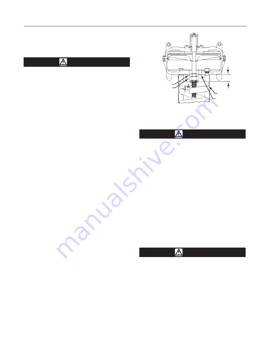
Figure 4. Dimension B for Spring Adjustment

LOWER DIAPHRAGM
CASING

SPRING SEAT

JAM NUT

ADJUSTING NUT

A0950-1 / IL

B

Size 100

CAUTION

The actuator must be in the vertical
position when adjusting spring to avoid
damage to thrust bearing (key 35, figure
6) and to properly position spacers re-
quired for adjustment.

Remove the shroud plate (key 107, figure 6), and loos-
en the jam nut (key 115, figure 6).

For small spring forces, adjustments can be made by
rotating the adjusting nut (key 114, figure 6). Clock-
wise rotation (when viewed from diaphragm casings)
of the adjusting nut will increase the loading pressure
required to start actuator stem travel, and counter-
clockwise rotation will decrease the pressure required
to start travel. Tighten the jam nut when adjustment is
complete.

For high spring forces, it is necessary to use spacers
between the lower diaphragm casing and the spring
seat to isolate spring force from the adjusting nut.

WARNING

To avoid personal injury from the com-
pressed actuator spring snapping back
to its original length, make and use the
spacers by following the instructions in
the steps below.

1.  It is recommended that three spacers be made of
3-inch schedule 80 pipe cut to the appropriate length
specified in step 2. If other than the recommended
material is to be used, be certain that the spacers are
capable of withstanding the spring force involved. The
spacers must be of equal length with ends cut squarely.

Summary of Contents for 657 Sizes 100

Page 1: ...0 Side Mounted Handwheel Assembly 9 Size 80 Hydraulic Snubber 9 Size 80 Top Mounted Handwheel 10 Size 80 Top Mounted Handwheel Disassembly 10 Size 80 Top Mounted Handwheel Assembly 10 Size 100 Top Mou...

Page 2: ...llow for typical regulator supply settings and or relief valve tolerances Scope of Manual This instruction manual provides information on instal lation adjustment maintenance and parts ordering for th...

Page 3: ...he stem con nector can result in stripped threads or improper operation Be sure that the length of each stem clamped in the stem connector is equal to or greater than the diameter of that stem Figure...

Page 4: ...r band key 60 figure 5 insert a rod of approximately 1 2 inch 12 7 mm diameter into a hole in the adjusting screw key 12 figure 5 and rotate the adjusting screw with the rod Rotating the screw from le...

Page 5: ...necessary The frequen cy of inspection and replacement depends on the se verity of service conditions Because of the care Fisher Controls takes in meeting all manufacturing re quirements such as heat...

Page 6: ...ing flange key 36 with Never Seez Nickel Special lubricant key 244 or equivalent Replace the adjusting flange adjusting screw and thrust bearing keys 36 12 and 35 Pack bearing with Lubriplate MAG 1 lu...

Page 7: ...below and carefully remove casing cap screws key 22 step 7 below 1 Remove shroud plate key 107 loosen jam nut key 115 and rotate adjusting nut key 114 until spring compression is relieved Note To reli...

Page 8: ...plate Note When you replace actuator diaphragms in the field take care to ensure the dia phragm casing bolts are tightened to the proper load to prevent leakage but not crush the material Perform the...

Page 9: ...45 threads with Never Seez Nickel Special key 244 or equivalent lubricant and slide the shaft into the gear case so that the end of the shaft fits snugly in the back worm retainer 4 Insert the bearing...

Page 10: ...ht to left until spring compression is relieved Rotate handwheel to be sure it is not com pressing actuator spring 3 Unscrew cap screws key 141 and remove hand wheel assembly 4 Remove hex nut key 54 a...

Page 11: ...etainer with the hole in the gear case insert the set screw key 41 and tight en 5 Slide the handwheel onto the worm shaft key 45 and install retaining ring key 118 6 Pack the two thrust bearings key 6...

Page 12: ...side mtd handwheel Std 3K664819042 w lower boss tapped 3L921219042 Steel w o side mtd handwheel 3L448522012 w side mtd handwheel 3N364522012 Size 80 5H yoke Cast Iron w o side mtd handwheel Std 18A549...

Page 13: ...l 2 in 51 mm travel 2 req d 10A2606X012 3 in 76 mm travel 2 req d 1N538238992 4 in 102 mm travel 2 req d 1U372738982 19 Nameplate stainless steel 12B6508X0A2 20 Drive Screw stainless steel 4 req d 1A3...

Page 14: ...ide mtd handwheel 2H733619042 w side mtd handwheel 2H733519042 Steel Key Description Part Number 36 Adjusting Flange cont d w o side mtd handwheel 2L448122012 w side mtd handwheel 2L524422012 60 Cover...

Page 15: ...Bushing brass Size 100 20A2582X012 112 O Ring nitrile 2 req d Size 100 1H8627X0042 113 O Ring nitrile Size 100 1R834206992 114 Hex Nut pl steel Size 100 10A2618X012 115 Hex Jam Nut pl steel Size 100 1...

Page 16: ...65 Gear Case Cast Iron 3H735319042 Steel 3N101922012 66 Bearing Gear Retainer steel 1H735024392 67 Thrust Bearing 2 req d 1H735499012 Key Description Part Number 68 Cap Screw pl steel 6 req d 1H2151X...

Page 17: ...544424052 125 Hex Jam Nut cd pl steel 6 req d 1A351124122 126 Woodruff Key steel 1J464728992 127 Slot Cover plastic 10A2598X012 Figure 8 Top Mounted Handwheel for Size 80 Actuator APPLY LUB CV8009 E D...

Page 18: ...Iowa 50158 USA Cernay 68700 France Sao Paulo 05424 Brazil Singapore 128461 Printed in U S A EFisher Controls International Inc 1973 1999 All Rights Reserved Fisher Fisher Rosemount and Managing The P...

Reviews: