Type 4000
10
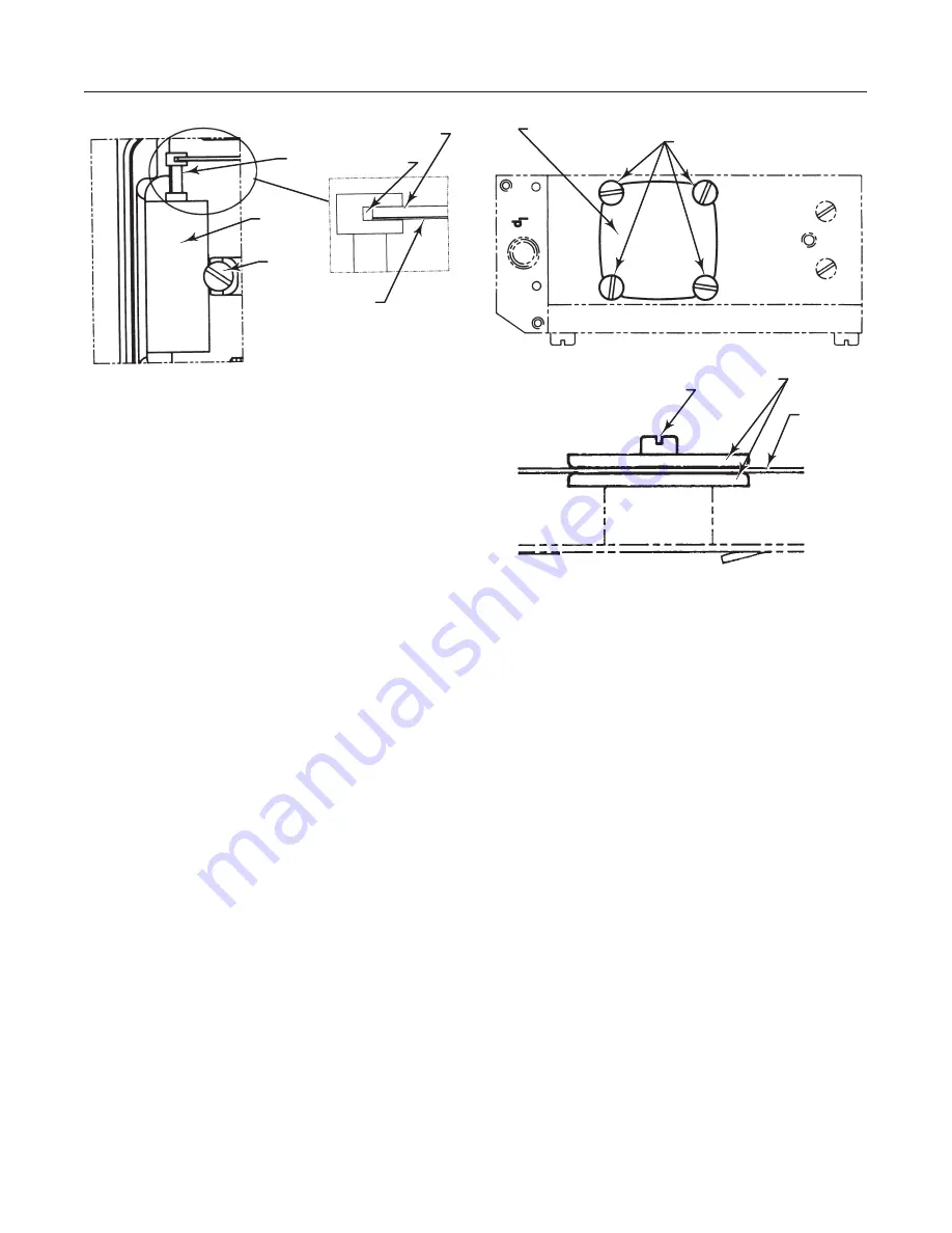
Figure 12. Pilot Valve Assembly
SCREW
PILOT
VALVE
ASSEMBLY
SPOOL
SPOOL GROVE
BALANCE ARM
LEAF SPRING
A7200 / IL
5. Check the O-rings, then secure and install the pilot
valve assembly to the positioner housing and secure it
with the screw. Make sure that the leaf spring on the
balance arm is properly fitted in the spool groove.
6. Check again to insure smooth operation of the as-
sembly.
Replacing the Diaphragm
Refer to figure 13.
1. Loosen the four screws and remove the diaphragm
cover.
2. Loosen the screw that secures the diaphragm. Re-
move the diaphragm and washers.
When installing the diaphragm make sure to place one
washer on each side of the diaphragm. Make sure that
the raised circle on the washers is facing the dia-
phragm.
3. Install the screw and tighten.
4. Check the O-ring on the diaphragm cover, then
install and secure the cover with the four screws.
Replacing Gauges
1. Shut off supply pressure and process lines to the
positioner.
2. Remove the defective gauge from the adapter
housing.
3. Coat the threads of the replacement gauge with a
sealant (Zink plate No. 770 or equivalent).
Figure 13. Diaphragm
DIAPHRAGM COVER
SCREWS
SCREW
WASHERS
DIAPHRAGM
A7201 / IL
4. Screw the replacement gauge into the adapter
housing gauge connection.
5. Apply supply pressure to the positioner. Using a
soap solution, check around the ports and connections
for leaks.
Removing the Positioner
1. Shut off supply pressure and process lines to the
positioner.
2. Remove the actuator cover.
3. Remove the flathead screw that secures the feed-
back lever to the positioner spindle. Remove the feed-
back lever from the spindle.
4. Refer to figure 3. Remove the four mounting
screws from the bottom of the adapter housing.
5. Lift the positioner off the adapter housing.
Replacing the Positioner
1. Replace the positioner on the actuator by perform-
ing the mounting and connection procedures in the
“Installation” section.
2. Calibrate the positioner by performing the proce-
dures in the “Calibration” section.


