Fisher 2502 Series Level-Trol Instruction Manual Download Page 8

2502 Series

8

expands and contracts the same amount as the mea-
sured liquid to nullify signal changes that would be
caused by temperature changes.

This type of displacer is shipped in a separate carton
but crated with the rest of the assembly. See the ap-
propriate sensor manual for filling instructions.
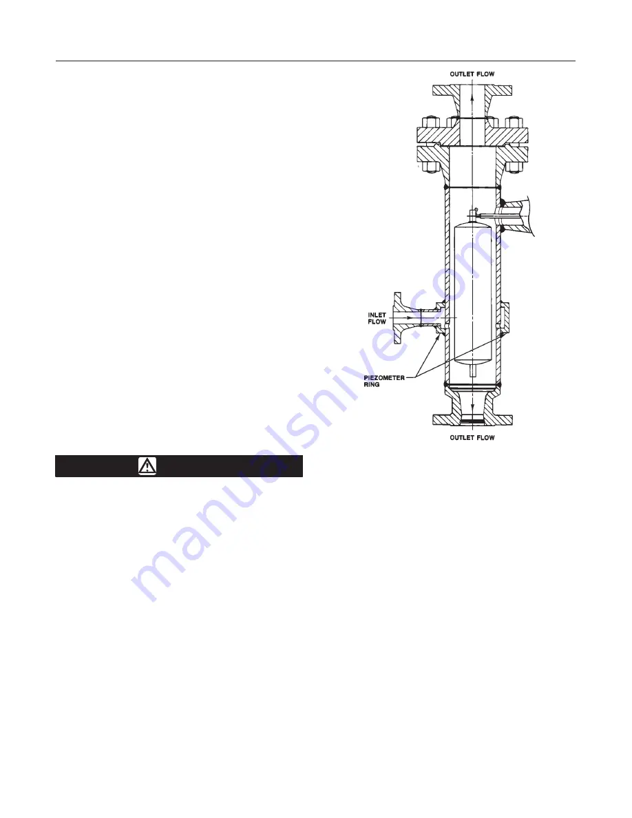
Piezometer Ring

A piezometer ring (figure 10) is used when it is desir-
able to measure the specific gravity of a liquid in a
flowing line, and when the liquid velocity exceeds two
feet/minute (10 mm/second) past the displacer in the
cage. The piezometer ring reduces the velocity effects
caused by liquid passing through the displacer cage.

To install this type of sensor, connect a line to the
cage inlet and outlet piping at each end of the cage.
Use hand valves to balance the liquid flow through the
cage and keep the displacer cage filled. It is advisable
to provide a rotameter or sight flow gauge for measur-
ing velocity through the cage. If the flow rates are
properly balanced, the transmitter output will show
little change when flow through the cage is shut off. If
the flow rate through the cage is too high the turbu-
lence may cause an erratic output pressure signal.
Readjust hand valves to stabilize the output pressure
signal.

Regulator Supply Pressure

WARNING

Do not overpressurize any system com-
ponent. Personal injury or property
damage may occur due to sudden pres-
sure release or explosion. To avoid
damage, provide suitable pressure-re-
lieving or pressure limiting devices if
supply pressure can exceed the maxi-
mum supply pressure listed in table 1.

Personal injury or property danage may
occur from an uncontrolled process if
the supply medium is not clean, dry, oil-
free, or non-corrosive gas. Industry in-
strument air quality standards describe
acceptable dirt, oil, and moisture con-
tent. Due to the variability in nature of
the problems these influences can have
on pneumatic equipment, Fisher Con-
trols has no technical basis to recom-
mend the level of filtration equipment
required to prevent performance degra-
dation of pneumatic equipment. A filter
or filter regulator capable of removing

Figure 10. Piezometer-Ring Cage for Flow Line Mounting

A1317-1/IL

particles 40 microns in diameter will suf-
fice for most applications. Use of suit-
able filtration equipment and the estab-
lishment of a maintenance cycle to
monitor its operation is recommended.

Standard 2502 Series controllers come complete with
supply and output pressure gauges and an integrally
mounted Type 67FR regulator to reduce supply pres-
sure from a maximum of 250 psig (17.3 bar) to the 20
or 35 psig (1.4 or 2.4 bar) required. This regulator has
built-in relief and a standard 40-micron to remove par-
ticles from the supply source.

The output pressure connection is on the back of the
controller case (figure 3). Pipe the supply pressure to
the in connection of the regulator mounted to the case
back. Provide a clean, dry, and noncorrosive air or gas
supply to the controller as follows:

After pressure connections have been made, turn on
the supply pressure and check all connections for
leaks.

Summary of Contents for 2502 Series Level-Trol

Page 1: ...n Requirements 11 Wet Calibration 11 Dry Calibration 11 Controller and Torque Tube Arm Disassembly 11 Determining Suspended Weight for Calibration 12 Calibration Procedure 12 Startup 13 Principle of Operation 13 Type 2502 Controller 15 Type 2502F Controller with Reset Relief Valve 15 Figure 1 Type 2502 Controller Mounted on Type 249B Sensor W3121 3 IL TYPE 249B SENSOR TYPE 2502 CONTROLLER Maintena...

Page 2: ... or density increases the output signal S Reverse Action Decreasing liquid or interface level or density increases the output signal A factory sup Figure 2 Guidelines for Use of Optional Heat Insulator Assembly USE INSULATOR CAUTION IF AMBIENT DEWPOINT IS ABOVE PROCESS TEMPERATURE ICE FORMATION MAY CAUSE INSTRUMENT MALFUNCTION AND REDUCE INSULATOR EFFECTIVENESS 0 20 40 60 80 100 120 140 160 0 10 2...

Page 3: ...onal band setting of 100 percent At 35 psig 2 4 bar Minimum 7 scfh 0 2 m3 h at proportional band setting of 0 or 200 percent Maximum 42 scfh 1 1 m3 h at proportional band setting of 100 percent Performance Hysteresis 0 6 percent of output pressure change at 100 percent of proportional band Repeatability 1 0 2 percent of displacer length or displacement force change Dead Band 1 0 05 percent of prop...

Page 4: ...amp ing plate For screwed connections use a 1 2 inch Figure 3 Pressure Connections 1 4 18 NPT SUPPLY CONNECTION ADJUSTING SCREW FILTER WELL DRAIN VALVE LOCKNUT 1 4 18 NPT OUTPUT CONNECTION VENT PRESSURE REGULATOR CD1700 E A1909 1 IL 12 7 mm hexagon wrench to unscrew the damping plate For flanged connections use a screwdriver to pry the damping plate out of the flange A cageless sensor is shipped w...

Page 5: ...level applications position the sen sor so that the line marked FLOAT CENTER on the cage is located as close as possible to the center of the liquid level or interface level range being mea sured For liquid or interface level applications it is advanta geous to install a gauge glass either on the vessel or on the sensor cage if the cage is tapped for a gauge With flanged connections use standard g...

Page 6: ...Note If the controller is not mounted on the sensor refer to the Installing Controller on Sensor section That section also provides instructions for adding a heat insulator to a unit If the sensor has a temperature compensated displacer or piezometer ring refer to the special constructions procedures in this sec tion before proceeding Attach a cageless sensor to a flanged connection on the vessel ...

Page 7: ... shows the installation of a top mounted cage less sensor The displacer may be attached to the dis placer rod before installing the sensor on the vessel Where the displacer diameter is small enough it may be desirable to install a long or sectionalized displacer through the sensor head access hole after the sensor is installed on the vessel Connect the displacer as shown in figure 8 locking the as...

Page 8: ...able pressure re lieving or pressure limiting devices if supply pressure can exceed the maxi mum supply pressure listed in table 1 Personal injury or property danage may occur from an uncontrolled process if the supply medium is not clean dry oil free or non corrosive gas Industry in strument air quality standards describe acceptable dirt oil and moisture con tent Due to the variability in nature ...

Page 9: ...ler out of service Adjustment locations are shown in figure 11 unless otherwise indicted When performing the checks open loop conditions must exist One way to obtain an open loop is to ensure that there is no flow through the final control element Another way to obtain an open loop is to disconnect the controller output signal line and plug the output connection During startup it is necessary to c...

Page 10: ...rmine the dial setting by moving the nameplate slide until the specific gravity on scale B is opposite the displacer volume on scale A Choose the percentage of displac er length as measured from the displacer bottom that you desire the liquid or interface level to cover Locate this percentage on scale D and read up from this per centage to find the raise level dial setting on scale C For example w...

Page 11: ... which the unit was designed To calibrate a controller it is necessary to place the device into operation This may be done on the vessel with the actual service liquid It may also be done in the shop but other means of obtaining a displacement force change must be provided It must be done in the shop if the process variable is not available for calibra tion or if the process cannot be varied for c...

Page 12: ...llowable substitute weight Ws that can be used with your particular construction To determine the total weight that must be suspended from the displacer rod to simulate a certain condition of liquid level or specific gravity solve the following equation Ws Wd 0 0361 V SP GR where Ws Total suspended weight in pounds should never be less than 0 5 pounds For a unit with a horizontal displacer make su...

Page 13: ...nal band knob to zero 4 Set the liquid at the minimum limit dry displacer 5 Turn the raise level knob to zero 6 Adjust the nozzle until output pressure is between 0 and 3 psig for a 3 to 15 psig signal range 0 and 0 2 bar for a 0 2 to 1 0 bar signal range or 0 and 6 psig for a 6 to 30 psig signal range 0 and 0 4 bar for a 0 4 to 2 0 bar signal range 7 Set the liquid at the maximum limit covered di...

Page 14: ...rks Type 2502 Controller As long as inflow and outflow of the vessel are equal the beam and flapper remain motionless and allow sup ply pressure to bleed through the nozzle as fast as it enters the relay through the fixed restriction A level or density change either raises or lowers the displacer and pivots the beam and flapper with respect to the nozzle An increase in level or density with direct...

Page 15: ...set Relief Valve This construction figure 13 has a differential relief valve used to prevent proportional pressure from ex ceeding reset pressure by more than a set value a feature useful for intermittent control applications Pro portional valve output registers in the outer chamber of the relief valve as well as in the proportional bellows ...

Page 16: ...nsors Due to the care Fisher Con trols takes in meeting all manufacturing requirements heat treating dimensional tolerances etc use only replacement parts manufactured or furnished by Fish er Controls WARNING Personal injury or property damage due to sudden release of pressure contact with hazardous liquid fire or explosion can be caused by puncturing heating or repairing a displacer that is retai...

Page 17: ...id lower the vessel level below the torque tube arm before pro ceeding For closed vessels release any pressure that may be above the liquid Also be careful to avoid overloading a thin wall torque tube and or overweight displacer Refer to figure 16 for key number locations 1 Remove the controller as described previously 2 A controller is attached to the sensor in one or the other of the mounting po...

Page 18: ...2 5 Process variable changed 2 5 Insure the process variable has not changed from original calibration settings or displacer not design specific gravity of process 2 5 Change process variable back to original sepcification or recalibrate If necessary provide replacement displacer of correct size and recalibrate 3 Controller cannot attain full output range 3 1 Supply pressure not set correctly 3 1 ...

Page 19: ... sensor 2 Remove the bearing assembly key 12 from the case key 1 3 Carefully slide the controller case straight in guid ing the bearing assembly key 12 operating arm base or pointer assembly key 68 or 51 figure 16 over the rotary shaft and easing an attached heat insulator over the shaft coupling key 36 figure 14 if necessary Se cure the case or insulator to the torque tube arm with the four cap s...

Page 20: ...and install the proportional band adjustment assembly Changing Relay The relay may be removed for cleaning or repair and must be taken off to remove the lower bellows 1 On a controller with indicator assembly loosen the two lower screws key 96 figure 17 of the relay case and slide out the indicator base plate key 53 figure 16 2 Disconnect the tubing key 11 figure 16 from the relay 3 Remove both mo...

Page 21: ...iaphragm so that the lugs on the casing and spacer ring line up and are also lined up with the body lug 10 Install the casing screws and tighten them slowly to ensure a good seal 11 Install the assembled orifice assembly and install the relay according to the Changing Relay section Parts Ordering Whenever corresponding with the Fisher Controls sales office or sales representative about this equip ...

Page 22: ...2502 Series 22 Figure 16 2502 Series Controller Constructions 30A8942 H DOC 43A2366 H DOC 30A8943 H DOC ...

Page 23: ...65 25072 68 Operating Arm Base brass pl Types 2502 and 2502F only 1J4166 14022 Key Description Part Number 69 Level Set Pivot Pin stainless steel 1J4167 35162 70 Pivot Base steel pl 19A9689 X012 71 Spring Washer stainless steel 1H8851 X0012 72 Washer stainless steel Types 2502 and 2502FC 2 req d 1E8730 X0012 Type 2502C 4 req d 1E8730 X0012 74 Washer stainless steel 6 req d 6100057 0X12 75 Reset Tu...

Page 24: ... 92 Relay spring steel pl 1C8961 27012 93 Valve Spring stainless steel 0X0836 37022 94 Spring Plate Gasket Standard neoprene 1H2696 03012 High temperature rubber 1K7000 04142 95 Spring Plate steel pl 1H2697 25072 96 Machine Screw stainless steel 6 req d 1A3294 X0022 97 Machine Screw stainless steel 4 req d 1A8664 X00A2 98 Washer standard only stainless steel 6 req d 1P8261 X0012 99 Bottom Gasket h...

Reviews: