


167D Series
4
Product Description
The 167D Series switching valves are pneumatically
operated and controlled units, built with a wide range of
capabilities to handle those switching applications that
involve venting, on-off control, and failure modes.
• The Types 167D and 167DS are two-way
switching valves.
• The Types 167DA and 167DAS are three-way
switching valves.
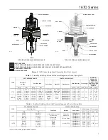
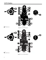
Principle of Operation
Refer to Figure 2 and also refer to Figures 3 through
5 for port D location. Control pressure enters the
switching valve through port D (not shown in Figure 2)
and registers under the diaphragm. Control pressure
overcomes the spring force and the diaphragm and
raise the valve plug, closing port C and opening port B
of the Type 167DA three-way switching valve. In this
condition, the Type 167D construction is turned off and
the Type 167DA construction provides flow from path
A to B. If, either intentionally or through pneumatic
failure, the control pressure drops below the spring
force, the diaphragm and valve plug move downward,
opening port C and closing port B of the Type 167DA
three-way switching valve. In this condition both
constructions provide a flow path from port A to
port C. The pressure change necessary to switch the
valve depends on the spring used and the setting of
the adjusting screw on the switching valve.
Overpressure Protection
The 167D Series switching valves have maximum
outlet pressure ratings that are lower than their
maximum inlet pressure ratings. A pressure-
relieving or pressure-limiting device is needed if inlet
pressure can exceed the maximum outlet pressure
rating. Overpressuring any portion of a switching
valve or associated equipment may cause leakage,
parts damage, or personal injury due to bursting of
pressure-containing parts or explosion of accumulated
gas. Switching valve operation within ratings does
not preclude the possibility of damage from external
sources or from debris in the pipeline. A switching
valve should be inspected for damage periodically and
after any overpressure condition.
Installation
Note
If the switching valve is shipped
mounted on another unit, install that
unit according to the appropriate
Instruction Manual.
!
WARNING
Personal injury, property damage,
equipment damage, or leakage due to
escaping gas or bursting of pressure-
containing parts may result if this
switching valve is overpressured or
is installed where service conditions
could exceed the limits given in the
Specifications section, or where
conditions exceed any ratings of the
adjacent piping or piping connections.
To avoid such injury or damage,
provide pressure-relieving or pressure-
limiting devices (as required by the
appropriate code, regulation, or
standard) to prevent service conditions
from exceeding those limits.
Before installing a Type 167D, 167DA, 167DS, or
167DAS switching valve, be sure the installation
complies with the following installation guidelines:
1. Switching valve operation within ratings does not
preclude the possibility of damage from debris in
Table 3.
Flow and Sizing Coefficients
TYPES
BODY SIZE
PORT
WIDE-OPEN FLOW COEFFICIENTS
C
1
IEC SIZING
COEFFICIENTS
C
g
C
v
X
t
167D, 167DS
1/4 NPT
C
41.46
1.09
37.56
0.89
1/2 NPT
46.50
1.18
39.03
0.96
167DA, 167DAS
All sizes
B
27.79
0.96
28.74
0.52
1/4 NPT
C
49.35
1.60
30.58
0.59
1/2 NPT
58.86
1.81
32.22
0.66