background image

Service Manual 547226: OB30 


                             December 2012 


 70   


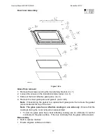
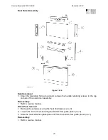
Door Outer Assembly 


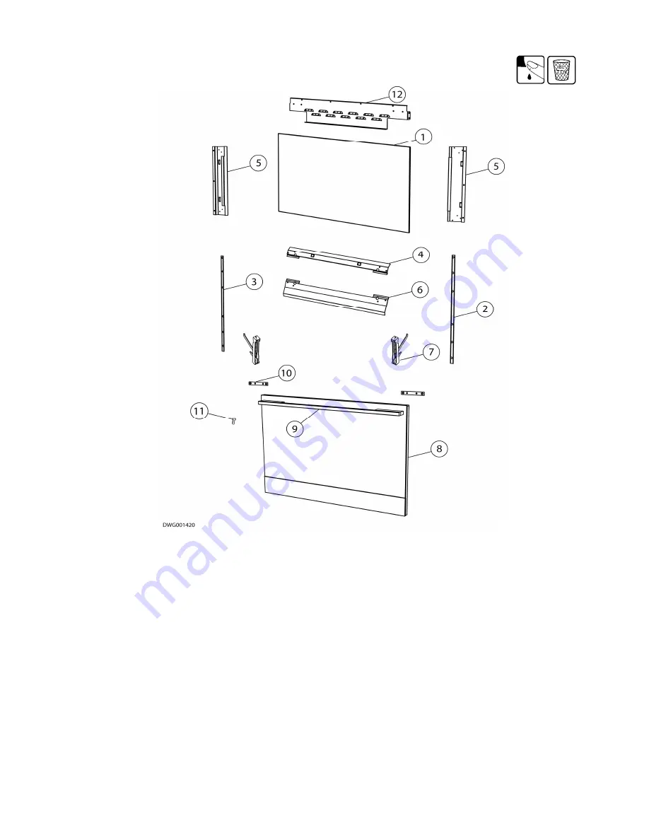
Figure 7.22b


Handle removal 
1.  Clear  the  insulation  from  around  and  remove  the  handle  retaining  screws  in  the  top 

corners of the outer door assembly.  

Reassembly 

  Refit in reverse manner.  

Glass Pane removal 
1.  Remove the screws securing the heat shield panel. (no. 4) 

2.  Loosen the four screws securing the bottom flow guide panel. (no. 6) 

3.  Slide the heat reflective glass pane out from the bottom flow guide panel. (no. 1)  

Reassembly 

  Refit in reverse manner.  

Summary of Contents for OB30DDEPX1

Page 1: ...Service Manual Wall Oven USA 547226 Models OB30DDEPX1 OB30SDEPX1 Product Codes 88491 88492 88535 88536 ...

Page 2: ......

Page 3: ... is indicated by the date and letter and replaces any earlier editions Model Service version Description Product code Market OB30DDEPX1 A Double oven brushed stainless steel graphite enamel self clean cycle 88491 US CA OB30SDEPX1 A Single oven brushed stainless steel graphite enamel self clean cycle 88492 US CA OB30DDEPX1 A Double oven brushed stainless steel graphite enamel clean cycle 88535 US C...

Page 4: ... 2 13 FAN ELEMENT 13 2 14 TEMPERATURE SENSOR 14 2 15 HALOGEN BULBS 14 2 16 MEAT PROBE SOCKET 14 2 17 DOOR LOCK MOTOR 14 2 18 TEMPERATURE SWITCH MODULE 15 2 19 TEMPERATURE L C D MODULE 15 2 20 FUNCTION SWITCH MODULE 15 2 21 FUNCTION L C D MODULE 15 2 22 CLOCK MODULE 15 2 23 POWER MODULE 16 2 24 POWER TRANSFORMER 16 2 25 COOLING FAN RESISTOR 16 2 26 THERMAL LIMITERS 17 2 27 ISOLATING RELAY 18 2 28 X...

Page 5: ... 5 13 SYMPTOM FAULT CODE F1 DISPLAYED IN TECH SELECT ONLY 37 5 14 SYMPTOM FAULT CODE F2 DISPLAYED 37 5 15 SYMPTOM FAULT CODE F3 DISPLAYED 37 5 16 SYMPTOM FAULT CODE F4 DISPLAYED 37 5 17 SYMPTOM FAULT CODE F5 DISPLAYED 38 5 18 SYMPTOM FAULT CODE F7 DISPLAYED 38 5 19 TRACING COOLING FAN FAULTS 38 5 20 TRACING OVEN CAVITY FAN FAULTS 39 5 21 TRACING OVEN LIGHT FAULTS 39 5 22 TRACING ELEMENT FAULTS 40 ...

Page 6: ...16 COOLING FAN 66 7 17 VENT FAN 66 7 18 OVEN CAVITY FAN 67 7 19 FAN SHROUD 67 7 20 RUNNERS 68 7 21 OVEN DOOR 68 7 22 OVEN DOOR DISASSEMBLY 68 7 23 MEAT PROBE SOCKET 71 7 24 OVEN DOOR LOCK ASSEMBLY 72 7 25 COMPONENT LOCATION GUIDE 73 8 N O T E S 74 ...

Page 7: ...ng then extreme care should be taken not to make contact with electrical components other than with testing probes Ensure the oven is turned off when removing any electrical component or connection 1 1 2 Electrostatic Discharge An anti static strap is to be used as electrical static discharge ESD protection when servicing electronic components 1 1 3 Good Working Practices Ensure the work areas are...

Page 8: ...o be used as E S D protection when replacing or handling electronic components 1 2 2 Fisher Paykel Smart Tool Handheld computer supplied in protective case with F P diagnostics software and service information loaded P N 813140 includes light pen P N 425930 Refer CBW website for compatible devices www cbw fp co nz ...

Page 9: ... 16 405mm Cavity Volume 3 5 cu ft 0 1 m 2 4 Location of Serial Plate The product serial plate is located on the left hand side behind the grill between the control panel and the oven door top oven door on dual oven models 2 5 Model Number Descriptions Product Code Service Version The model number contains the following information eg OB30DDEPX1 Type OB Oven Built in Width 30 30 inches Cavity D Dou...

Page 10: ...sists of three letters and six digits and contains the following information Example U I P 123456 Sequential Serial Number Manufacturing Plant Code FISHERPAYKUL Code indicates month of manufacture CUMBERLAND Code indicates year of manufacture Cumberland Code Letter C U M B E R L A N D Year 1 2 3 4 5 6 7 8 9 0 Fisherpaykul Code Letter F I S H E R P A Y K U L Month 1 2 3 4 5 6 7 8 9 10 11 12 Manufac...

Page 11: ...attage 35 watts Frequency 60 HZ 2 8 Cooling Fan The cooling fan will turn on as soon as the oven mode dial is moved from the OFF position It will turn off after eight seconds if a temperature isn t selected The cooling fan will only turn off if the oven cavity has cooled below 300 F 150 C after use If the oven cavity temperature is above 550 F 290 C the cooling fan will run at high speed During th...

Page 12: ... top speed refers to single ovens or the cavity being used in a double oven 2 9 Active Vent Fan Exhaust Fan The vent fan will operate for the first thirteen minutes of all oven modes except Warm does not operate and Self Clean Cycle Broil Grill modes runs continuously Voltage 220 240 VAC Frequency 50 60 HZ Wattage 18 watt 2 10 Outer Broil Grill Element The outer broil grill element will turn on ei...

Page 13: ...ement is concealed under the cavity base and will turn on eight seconds after the mode is selected Operational Modes True Aero pre heat assistance only Bake Aero Bake Warm Pastry Bake Aero Pastry Roast Self Clean Voltage 220 240 VAC Wattage 1500 watt 2 13 Fan Element The fan element and oven fan will turn on eight seconds after the mode is selected Operational Modes True Aero Bake pre heat assista...

Page 14: ...turn off when the door is closed if no oven mode is selected or if the programmed oven cook time has finished There are three soft start halogen bulbs in each oven cavity Voltage 12 VAC Wattage 20 watt 2 16 Meat Probe Socket Voltage 5 VDC Figure 2 18 2 17 Door Lock Motor The door lock will only operate during the Self Clean Cycle and is designed to stop the oven door being opened when very high te...

Page 15: ...re 2 21 2 20 Function Switch Module The function switch module sets the oven mode to be used It has a data link to the clock module Current Draw 72 mA Figure 2 22 2 21 Function L C D Module The function LCD module is controlled by the clock module It displays the oven mode selected by the function switch module Current Draw 72 mA Figure 2 23 2 22 Clock Module The clock module contains a flash micr...

Page 16: ...drives oven lights fans elements and lock motors It also monitors the sensors and micro switches and provides power to the control panel Voltage 12 VAC 2 24 Power Transformer Voltage 12v 120v 60hz Refer fig 8a 2 25 Cooling Fan Resistor Power Rating 50 watt Resistance 220 Ohms Max Ambient Temp 185 F 85 C Refer fig 8a ...

Page 17: ...ripped there will be no continuity across its contacts Limiter Locations Figure 2 28a Note TL Thermal Limiter MTL Microtemp limiter Double ovens have thermal limiters TL1 TL2 and a microtemp limiter MTL Single ovens have thermal limiter TL1 and a microtemp limiter MTL Figure 2 28b MTL TL1 TL2 ...

Page 18: ... double oven They will cut power to the oven elements when tripped Capacity Rating 16 Amps at 12VDC Trip Temperatures 284 F 140 C Figure 2 28d 2 27 Isolating Relay Double Line Break Relay This relay switches the elements cavity fan and vent fan on the opposite side to the power module relay switches It is only energised when an oven mode is selected Coil Voltage 12 VDC Coil Input 1 watt Figure 2 2...

Page 19: ...ds of each minute the bake element is on and during the third fifteen seconds of each minute the Broil Grill outer element is on The cooling fan for the cavity being cleaned will be on high speed The cooling fan for the other cavity will be on low speed During the Self Clean Cycle in a double oven the cavity not being cleaned cannot be operated in any mode The oven heats for its cleaning temperatu...

Page 20: ...ionally during the first fifteen seconds of each minute the bake element is on and during the third fifteen seconds of each minute the Broil Grill outer element is on The cooling fan for the cavity being cleaned will be on high speed The cooling fan for the other cavity will be on low speed During the Self Clean Cycle in a double oven the cavity not being cleaned cannot be operated in any mode The...

Page 21: ... Low ON ON True Aero Remainder ON Low Low ON ON Preheat ON Low Low ON ON Aero Bake Remainder ON Low Low ON ON ON Preheat ON Low Low ON ON Bake Remainder Low Low ON 33 ON Preheat ON Low Low ON ON Aero Pastry Remainder ON Low Low ON ON Preheat ON Low Low ON ON Pastry Bake Remainder Low Low ON ON 1 Hi Low ON ON ON 2 Hi Low ON ON 3 Hi Low ON ON ON Self Clean 4 Hi Low ON ON Warm All ON Low Low ON ON ON...

Page 22: ...e When the mode is set the lights and cooling fan will come on 3 3 Temperature Dial and Display This is turned to select the desired temperature 3 4 Oven Modes The oven has 9 cooking modes plus Warm and Self Clean These use different combinations of elements and the oven fan as follows True Aero A concealed heating element surrounding the fan in the rear of the oven heats air which is then blown i...

Page 23: ...ner broil grill element Maxi Broil Grill Heat comes from both the upper inner and outer broil grill elements Aero Broil Grill Heat comes from both the upper inner and outer broil grill elements and is circulated throughout the oven cavity by the oven fan Self Clean Refer to Section 2 32 for an explanation of how this function operates 3 5 Active Vent and Cooling Fans The active vent fan operates i...

Page 24: ... turning the PUSH TO CLEAR button 7 Choose the cooking mode and temperature required These settings will automatically be adopted after 8 seconds or you can press the STOP TIME button Each of the steps in setting Automatic Delayed Time Cooking must be started within 8 seconds of the previous step being completed otherwise the clock display will revert to the time of day and the process will have t...

Page 25: ...s faiths that observe a no work requirement on the Sabbath When the oven is in Sabbath mode clock temperature and oven mode displays will be disabled no tones will sound no error messages or temperature changes will be displayed the oven cavity lights will remain in the same state on or off as when the Sabbath Mode is set To set the Sabbath mode 1 Enter the User Select mode 2 Turn the oven mode di...

Page 26: ...led To set the Short Alert 1 Enter the User Select mode 2 Turn the oven mode dial until Short Alert appears in the display 3 Press the PUSH TO CLEAR button to select either ON or OFF in the clock display 4 Press the CLOCK button to activate 3 13 Time Mode The clock display can be altered to show the time in either a 12 hour or 24 hour format To change the clock display 1 Enter the User Select mode...

Page 27: ... until Lang US appears in the display 3 Press the PUSH TO CLEAR button to select US EN FR SP or dC in the clock display 4 Press the CLOCK button to activate 3 16 Oven Reset This will reset the Temperature Scale Short Alert Time Mode and Show Clock to the default settings Sabbath Mode and Language settings will remain unaffected To reset 1 Enter the User Select mode 2 Turn the oven mode dial until ...

Page 28: ...ill not heat Note To disable the sales mode the oven will need to be switched off at the mains for at least 5 minutes to clear and the product will revert back to normal operation and elements will operate normally 4 2 Technician Mode Navigation To Enter Technician Mode 1 Ensure all oven modes and temperature displays are set to OFF 2 Ensure no cooking auto functions are set 3 Enter the User Selec...

Page 29: ... 16 CAVITY TEMP The Cavity Temperature measured by the sensor 17 FAULT CODE The two most recent Fault Codes are displayed Refer to Note 1 18 NUM DAYS Shows the number of days the product has been on 19 DOWN LOAD Shows that data can now be downloaded Press CLEAR to begin Smart Tool Download 20 TEMP OFFSET Adjust temperature to suit customer Press CLEAR to set Note When FAULT CODE is selected the ov...

Page 30: ...s Fault Information Sections There are four sections displaying information on the two most recent fault codes for each oven cavity The information contained details the oven settings electronic board temperatures and the status of all oven outputs at the time the fault occurred Status Section This section details all the current user settings and the electronic software and hardware details Also ...

Page 31: ...iew Section 2 25 Replace if there is no 12VAC Check for a tripped microtemp limiter and replace if tripped Check the other thermal limiters and trace the likely cause for tripping refer to Section 5 24 Check for a blown power module fuse by testing for 12VDC between pins 1 and 6 of the 12 way clock connector on the power module refer to Technical Overview Section 2 25 If there is no 12VAC then the...

Page 32: ...refer to Servicing Instructions Section 7 8 5 3 SYMPTOM Temperature or Oven Mode Switch Module is jammed or loose POSSIBLE CAUSES Assembly is incorrect Switch has failed DIAGNOSIS Check the switch module is assembled correctly and reassemble if required refer to Servicing Instructions Section 7 6 Replace the switch module if the fault can t be rectified refer to Servicing Instructions Section 7 6 ...

Page 33: ...le oven only POSSIBLE CAUSES Lower cavity power module has no power DIAGNOSIS Check the connection between upper and lower cavity power modules Test for the correct supply voltage to the lower cavity power transformer 120 volts Check the connection from the power transformer to the lower cavity power module Check for a blown power module fuse by testing for 12VDC between pins 1 and 6 of the 12 way...

Page 34: ...s refer to Section 5 20 Replace the power module if no other faulty components can be found refer to Servicing Instructions Section 7 9 Note the oven temperature can be recalibrated 20 F 10 C refer to section 4 5 5 8 SYMPTOM Baking burns on the top POSSIBLE CAUSES Incorrect oven use Incorrect temperature scale used Faulty temperature sensor Faulty oven element Faulty oven cavity fan Faulty power m...

Page 35: ...Check for oven element faults mainly bake element refer to Section 5 22 Replace the power module if no other faulty components can be found Refer to Servicing Instructions Section 7 9 5 10 SYMPTOM Oven seems to be functioning normally but does not heat POSSIBLE CAUSES Oven is in Sales Mode Refer to Section 4 0 Diagnostics Faulty oven door switch or door not closed Tripped thermal limiter Faulty te...

Page 36: ...efer to Section 5 23 Check for oven element faults refer to Section 5 22 Replace the power module if no other component faults can be found Refer to Servicing Instructions Section 7 9 5 12 SYMPTOM Oven Lights do not turn On Off POSSIBLE CAUSES Blown oven light bulb s Faulty oven door switch Faulty wiring Faulty power module DIAGNOSIS Replace bulb s if faulty If lights do not turn off check for ove...

Page 37: ...22 Replace the power module if no other component faults can be found refer to Servicing Instructions Section 7 9 5 15 SYMPTOM Fault Code F3 displayed CAUSE The oven temperature was sensed at over 600 F 315 C during normal cooking operation DIAGNOSIS Check for temperature sensor fault refer to Section 5 23 Check for oven element faults refer to Section 5 22 Replace the power module if no other com...

Page 38: ...l not start 1 Enter Technician Mode diagnostics to test the cooling fan operation refer to Diagnostics Section 4 3 The cooling fan will operate at low speed in normal operation When the cooling fan is turned on in diagnostics it will run at high speed 2 Test for the correct voltage across the cooling fan contacts or substitute the fan with a dummy load Replace the fan if tests are good refer to Se...

Page 39: ...E If light bulb is faulty 1 Replace halogen bulb refer to Servicing Instructions Section 7 13 If all the lights will not turn on or replacing the bulb s did not fix the problem 1 Check the continuity of the light wiring back to power module refer to Technical Overview Section 2 25 for light connector location Replace the lamp assembly if there is no continuity refer to Servicing Instructions Secti...

Page 40: ...r to Technical Overview Sections 2 10 2 15 2 33 to find out which elements are used for each oven mode 1 Check for a tripped thermal limiter refer to section 5 24 2 Test the element operation in Technician Mode refer to Diagnostics Section 4 3 3 If the element does not heat up in Technician Mode test the resistance of the element The appropriate range of resistance for each element is given in Tab...

Page 41: ... displayed reading is incorrect refer to Servicing Instructions Section 7 9 5 24 Tracing thermal limiter faults Refer to Technical Overview Section 2 28 Note In the event of a thermal limiter tripping it is important that the cause be located and rectified PROCEDURE 1 To locate the tripped thermal limiter check for continuity across the limiter contacts 2 Replace the faulty thermal limiter s with ...

Page 42: ...Instructions Section 7 23 Door Lock Switches Test to ensure the lock switch is switching properly 1 Use a multimeter to check that the door lock switch readings back to the power module are correct When the door is not locked Lock Switch 1 inputs should be short circuit and Lock Switch 2 inputs should be open circuit The readings are vice versa when the door is locked Figure 5 25 2 Check the conti...

Page 43: ...m the clock module 2 Remove the link harness to the lower cavity power module The clock module now assumes there is only one power module The second power module will run in a powered but disabled mode elements will not operate 3 Try to operate the upper cavity If the fault code reappears then the upper cavity power module is faulty and needs to be replaced refer to Servicing Instructions Section ...

Page 44: ...Service Manual 547226 OB30 December 2012 44 6 Wiring Diagrams 6 1 Double Oven Wiring Schematic ...

Page 45: ...Service Manual 547226 OB30 December 2012 45 6 2 Single Oven Wiring Schematic ...

Page 46: ...Service Manual 547226 OB30 December 2012 46 6 3 Double Oven Wiring Diagram Temperature Protection Circuit ...

Page 47: ...Service Manual 547226 OB30 December 2012 47 Neutral Circuit ...

Page 48: ...Service Manual 547226 OB30 December 2012 48 Generic High Voltage Circuit ...

Page 49: ...Service Manual 547226 OB30 December 2012 49 Generic Low Voltage Lock Circuit ...

Page 50: ...Service Manual 547226 OB30 December 2012 50 Lighting and Earth Circuit ...

Page 51: ...Service Manual 547226 OB30 December 2012 51 6 4 Single Oven Wiring Diagram Temperature Protection Circuit ...

Page 52: ...Service Manual 547226 OB30 December 2012 52 Neutral Circuit ...

Page 53: ...Service Manual 547226 OB30 December 2012 53 Generic High Voltage Circuit ...

Page 54: ...Service Manual 547226 OB30 December 2012 54 Generic Low Voltage Lock Circuit ...

Page 55: ...Service Manual 547226 OB30 December 2012 55 Lighting Earth Circuit ...

Page 56: ...t of the cavity onto a suitable support Warning This oven is heavy and care should be taken to use correct lifting techniques Reassembly Refit in reverse manner 7 2 Components in Control Panel Area 1 Remove the oven from the joinery cavity refer to Section 7 1 Warning To avoid the oven tipping forward remove the shelves utensils and doors Refer to Section 7 21 Note The oven does not need to be rem...

Page 57: ...tion 7 21 Note The oven does not need to be removed completely from the joinery cavity Sliding the oven out 8 inches 200mm will give sufficient access space 2 Remove the two screws fixing the service panel to the side panels 3 Lift off the service panel The power module and other electronic components will now be accessible Reassembly Refit in reverse manner Follow the reassembly procedure refer t...

Page 58: ...ossible crush points during reassembly Follow the reassembly procedure refer to Section 7 5 7 7 Function and Temperature L C D Modules and Lenses Location Control Panel L C D Modules Removal 1 Follow the general servicing instructions for components around the control panel area refer to Section 7 2 2 Remove the temperature oven mode knobs and the clock twist button 3 Disconnect the earth wire and...

Page 59: ... to Section 7 5 7 8 Clock Module or Buttons Location Control Panel Removal 1 Follow the general servicing instructions for components around the control panel area refer to Section 7 2 2 Remove the temperature oven mode knobs and the clock twist button 3 Disconnect the earth wire and remove the mounting panel 4 Disconnect the wiring harness and transfer to the replacement clock module or replace t...

Page 60: ... in order to lift the board up Re assembly Refit in reverse manner Follow the reassembly procedure refer to Section 7 5 Figure 7 9a 7 10 Power Transformer Location Under the service panel Removal 1 Follow the general servicing instructions for components around the service panel area refer to Section 7 4 2 Remove the top panel 3 Remove the two wires from the power supply terminal block and the two...

Page 61: ...Remove the oven fan shroud refer to Section 7 19 2 Remove the two screws securing the sensor to the oven cavity 3 Pull the sensor wires through hole in the oven cavity wall until the wire connector is accessible and disconnect the faulty sensor Reassembly 1 Push the excess wire back through the hole in the oven cavity 2 Refit in reverse manner Follow the reassembly procedure refer to Section 7 5 7...

Page 62: ...y retaining screws and the lamp holder retaining screws 4 Disconnect the lamp assembly wires at the connectors in the back panel area 5 Pull the lamp assembly wires out through the oven cavity Note String can be tied on the end of the light assembly wires to aid in feeding the new wires back through the holes in the side insulation panel Reassembly 1 Feed the new wire connectors back through the h...

Page 63: ...nal block in the top panel area 4 Remove the control panel refer to Section 7 2 5 Remove the three screws along the front of the wiring panel and the two screws either side fixing the wiring panel 6 Lift the front of the wiring panel to access the lamp assembly and wires 7 Remove the lamp holder retaining screws 8 Feed the wires through the hole in the wiring panel Figure 7 14b Reassembly 1 Refit ...

Page 64: ...so that the element terminals will clear the hole in the oven cavity 4 Disconnect the wires and connect to the replacement element Reassembly Refit in reverse manner Check the element operation refer to Diagnostics Section 4 3 Fan Element Location Rear of the oven cavity Removal 1 Remove the fan shroud refer to Section 7 19 2 Remove the screws securing the fan element to the rear of oven 3 Pull th...

Page 65: ...to Section 7 5 For Double Oven Upper Cavity 1 Remove the remaining section of vent ducting 2 Disconnect the lower vent fan wires 3 Remove the lower vent fan 4 Remove the element wires 5 Remove the two screws retaining the fan cover Figure 7 15b 6 Pull the fan cover with the cooling fan attached upward to clear the locating tabs 7 Allow the fan cover to drop down to clear the element 8 Remove the e...

Page 66: ... the locating slot 4 Remove the four small retaining screws for the cooling fan side brackets and transfer the brackets to the replacement cooling fan Note Check the replacement cooling fan is specified as in section 2 8 Reassembly Refit in reverse manner Follow the reassembly procedure refer to Section 7 5 7 17 Vent Fan Location In the back panel area Removal For single ovens and upper cavity in ...

Page 67: ...ection 7 19 4 Remove the oven fan blade Note Turn the fan blade securing nut clockwise to remove left hand thread 5 Remove the three fan motor mounting screws and remove the fan motor from the rear 6 Transfer the mounting plate to the replacement fan motor Note To remove the mounting plate use pliers to bend the holding tabs Reassembly Refit in reverse manner Follow the reassembly procedure refer ...

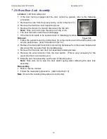
Page 68: ... load the top arm of the hinges 4 Lift the oven door out of the hinge slots Reassembly 1 Place the hinge arms into the hinge slots ensuring they lock into place 2 Ensure the oven door is opened fully unlock the upper arm from the hinge clips 3 Raise the door slightly and ensure the hinge clips are released from the upper arms 4 Check the door closes and seals correctly 7 22 Oven Door Disassembly T...

Page 69: ...ket no s 4 5 Note If transferring the gasket to a replacement glass pane then ensure the gasket join is located at the top of the door Note The glass pane has a reflective coating on one side only Ensure that the coating is facing the oven cavity when reassembled To test if a glass pane has a heat reflecting coating use an ohmmeter to test for continuity on the glass surface If there is continuity...

Page 70: ...taining screws in the top corners of the outer door assembly Reassembly Refit in reverse manner Glass Pane removal 1 Remove the screws securing the heat shield panel no 4 2 Loosen the four screws securing the bottom flow guide panel no 6 3 Slide the heat reflective glass pane out from the bottom flow guide panel no 1 Reassembly Refit in reverse manner ...

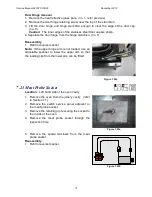
Page 71: ... reverse manner Note If the upper hinge arm is not loaded use an adjustable spanner to lower the upper arm so that the loading clip from the lower arm can be fitted Figure 7 22c 7 23 Meat Probe Socket Location Left hand side of the oven cavity 1 Remove the oven from the joinery cavity refer to Section 7 1 2 Remove the switch service panel adjacent to the meat probe socket 3 Remove the retaining nu...

Page 72: ... Follow the general servicing instructions for components around the back panel and service panel areas refer to Sections 7 3 7 4 2 Remove the door switch and lock motor wiring harnesses from the power module and disconnect the two wires from the isolating relay 3 Remove the front and rear door lock assembly retaining screws 4 Remove the wire connector from the door switch This is only necessary f...

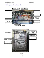
Page 73: ...de Power Transformer XY Capacitor Vent Fan Cooling Fan Isolating Relay Clock Module Power Module L C D Switch Modules Microtemp Limiter 93 C Broil Grill Elements Thermal Limiter 1 Thermal Limiter 2 Door Lock Assy Fan Element Oven Fan Motor Bake Element Figure 8a Figure 8a ...

Page 74: ...Service Manual 547226 OB30 December 2012 74 8 N O T E S ...

Reviews: