


321144
75
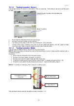
11 ICEMAKER & WATER DISPENSER SERVICE
PROCEDURES
Safety Considerations
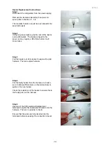
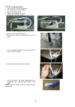
11.1 Component Replacement
11.1.1 Icemaker PCB Replacement
•
The icemaker PCB is fitted to the outside of the power/control module.
•
Disconnect the refrigerator from the power supply.
•
Remove the power/control module from the unit compartment.
•
Using a flat bladed screwdriver, lever the PCB cover from the power/control module.
NOTE:
Care should be taken, as too much pressure may cause the clip on the cover to break.
•
Remove the RAST connector from the icemaker PCB and remove the PCB.
•
Refit in reverse order.
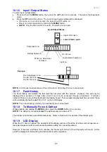
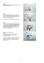
11.1.2 Icemaker Unit Removal
•
Disconnect the refrigerator from the power supply.
•
Remove all baskets/trays from the freezer.
•
Remove left hand side rail supports.
•
Remove the clip and insulation pad holding the icemaker sensor to the bottom of the ice tray.
•
Remove the sensor from under the icemaker tray.
•
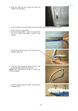
Place fingers at the rear of the icemaker and with a brisk downward motion pull the icemaker from the
roof of the freezer.
NOTE:
Both front and rear clips should have dislodged. If only the rear clip has dislodged, place fingers in
the front of the icemaker and once again briskly pull the icemaker down.
•
Disconnect the icemaker harness.
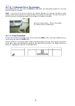
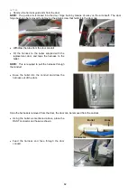
11.1.3 Refitting Icemaker
•
Refit the sensor to the underneath of the icemaker tray.
•
Refit the wiring connector.
•
Place the harness into the groove on the edge of the body of the icemaker.
•
Locate the clips and align the icemaker to the clips.
•
With an upward pressure, re-clip the icemaker.
NOTE:
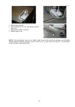
If either front or rear clips do not re-clip, further pressure will need to be exercised to re-clip the
icemaker.
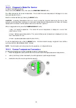
11.1.4 Icemaker Temperature Sensor Replacement
•
Remove the icemaker (refer to Section 11.1.2).
•
The sensor wires are to be cut as close to the sensor as possible. Strip the wires back 10mm (
3
/
8
inch) on the new sensor and on the wiring in the cabinet to allow the wires to be soldered or crimped
together.
•
Place heat shrink onto both wires of the sensor.
•
Solder the wires, slide the heat shrink over the joints and heat the heat shrink.
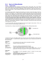
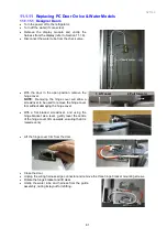
11.1.5 Water Valve Replacement
•
Ensure the water is turned off at the supply tap.
•
Disconnect the refrigerator from the power supply.
•
Pull the product away from the wall to access the rear of the product.
•
To remove the water tube from the water valve, push the inner part of the clip inwards and hold down
while pulling the tube from the valve. Drain the water (approximately 1½ litres) into a container.
•
Remove the RAST connector from the water valve.
•
Remove the two screws holding the valve to the back wall of the unit compartment.
•
Refit in reverse order.
CAUTION
ALL TERMINALS AND INTERNAL PARTS SHOULD BE TREATED AS LIVE.
ALL SERVICING SHOULD BE CARRIED OUT WITH THE REFRIGERATOR
DISCONNECTED FROM THE POWER SUPPLY.
Summary of Contents for 635 Active Smart
Page 1: ...321144 Service Manual 635 680 790 900 Active Smart Refrigerator Freezer R134a R600a Systems...
Page 2: ...321144 2...
Page 96: ...321144 96 Photo 12 22 5...
Page 100: ...321144 100 Diagram 12 25...
Page 108: ...321144 108 13 11 Embraco Compressor Fitted With External Overload Diagram 13 11...
Page 114: ...321144 114 14 2 Non Ice Water Models Wiring Diagram...
Page 116: ...321144 116 14 4 Ice Water Models Wiring Diagram...
Page 117: ...321144 117 14 5 900 Models Power Control Module Wiring Connections Reciprocating Compressor...
Page 118: ...321144 118 14 6 900 Models Wiring Diagram Reciprocating Compressor...
Page 119: ...321144 119 14 7 900 Models Power Control Module Wiring Connections VC Compressor...
Page 120: ...321144 120 14 8 900 Models Wiring Diagram VC Compressor...
Page 121: ...321144 121 14 9 B Model Wiring Route Diagram 14 9...
Page 122: ...321144 122 14 10 T Model Wiring Route Diagram 14 10...
Page 145: ......


