


321144
34
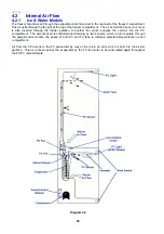
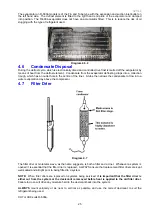
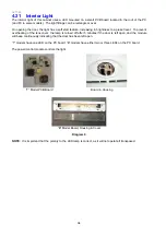
4.21 Interior Light
The interior light of this cabinet uses a LED mounted on a small PCB board located in the roof of the PC
(and FC in some models). The light fittings can be rectangle or oval.
On opening the door, the light has a soft start feature, increasing in brightness to a preset level. To prevent
overheating of the lens cover, the lamp is turned off after 5 minutes if the door is left open, and the module
will beep continuously indicating that the door has been left open.
“T” models have one LED on the PC board; “B” models have either two or three LEDs on the PC board.
The power/control module controls the light.
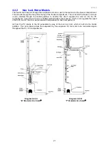
“T” Model PCB Board
Board in Housing
“B” Model Board, Housing & Cover
Diagram 0
NOTE:
It is important that the polarity to the LED lamp is correct, as it will not operate if transposed.
Summary of Contents for 635 Active Smart
Page 1: ...321144 Service Manual 635 680 790 900 Active Smart Refrigerator Freezer R134a R600a Systems...
Page 2: ...321144 2...
Page 96: ...321144 96 Photo 12 22 5...
Page 100: ...321144 100 Diagram 12 25...
Page 108: ...321144 108 13 11 Embraco Compressor Fitted With External Overload Diagram 13 11...
Page 114: ...321144 114 14 2 Non Ice Water Models Wiring Diagram...
Page 116: ...321144 116 14 4 Ice Water Models Wiring Diagram...
Page 117: ...321144 117 14 5 900 Models Power Control Module Wiring Connections Reciprocating Compressor...
Page 118: ...321144 118 14 6 900 Models Wiring Diagram Reciprocating Compressor...
Page 119: ...321144 119 14 7 900 Models Power Control Module Wiring Connections VC Compressor...
Page 120: ...321144 120 14 8 900 Models Wiring Diagram VC Compressor...
Page 121: ...321144 121 14 9 B Model Wiring Route Diagram 14 9...
Page 122: ...321144 122 14 10 T Model Wiring Route Diagram 14 10...
Page 145: ......


