


321144
111
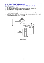
13.14 Compressor Fault Diagnosis
13.14.1 Compressor Won't Start - Dead (PTC Relay Fitted)
Checks to be carried out:
1. Check the fuse and power outlet.
2
Check that there is the correct voltage from the power/control module to the compressor.
3. Continuity test from the 3-pin plug, terminal block and harness to relay.
4. Check the overload for continuity.
5. Test the PTC Relay.
Remove it from the compressor, and using an ohmmeter check the resistance through the PTC itself
between M and S terminals or 2 and 3 terminals. The PTC will have a low resistance at a low
temperature (30-60 ohms at 18
O
C).
6. With the PTC removed, check the run and start windings of the compressor using an ohmmeter. Refer
to the compressor specifications page for these figures.
Diagram 13.14.1
Summary of Contents for 635 Active Smart
Page 1: ...321144 Service Manual 635 680 790 900 Active Smart Refrigerator Freezer R134a R600a Systems...
Page 2: ...321144 2...
Page 96: ...321144 96 Photo 12 22 5...
Page 100: ...321144 100 Diagram 12 25...
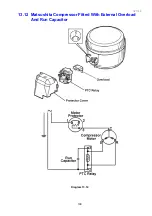
Page 108: ...321144 108 13 11 Embraco Compressor Fitted With External Overload Diagram 13 11...
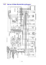
Page 114: ...321144 114 14 2 Non Ice Water Models Wiring Diagram...
Page 116: ...321144 116 14 4 Ice Water Models Wiring Diagram...
Page 117: ...321144 117 14 5 900 Models Power Control Module Wiring Connections Reciprocating Compressor...
Page 118: ...321144 118 14 6 900 Models Wiring Diagram Reciprocating Compressor...
Page 119: ...321144 119 14 7 900 Models Power Control Module Wiring Connections VC Compressor...
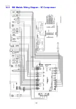
Page 120: ...321144 120 14 8 900 Models Wiring Diagram VC Compressor...
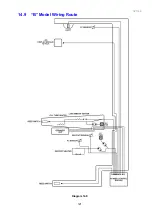
Page 121: ...321144 121 14 9 B Model Wiring Route Diagram 14 9...
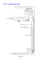
Page 122: ...321144 122 14 10 T Model Wiring Route Diagram 14 10...
Page 145: ......


