First Alert PRO-CM600 User Manual Download Page 5

Page  5

Installing camera

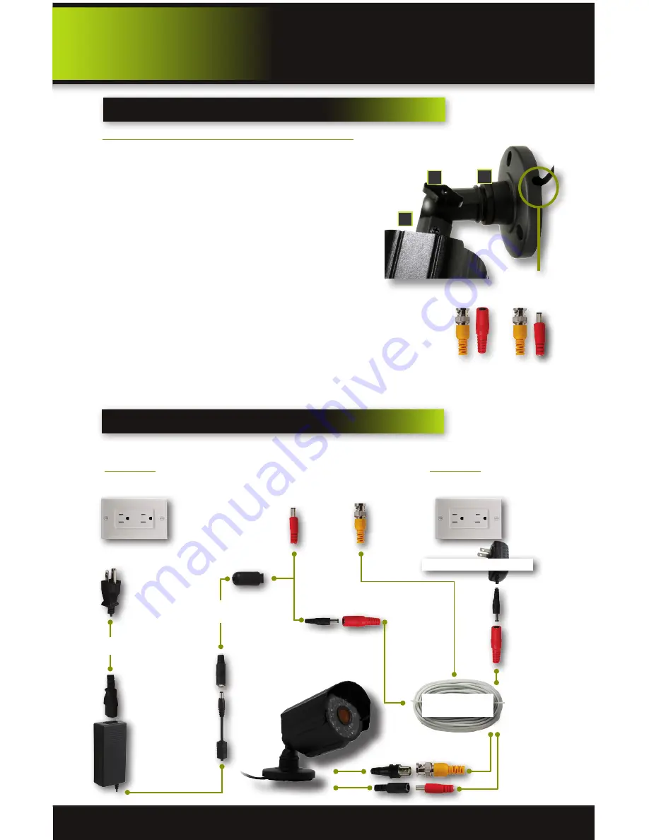
Installing Cable-Safe Mounting Bracket

Decide if the camera is to be wall or ceiling mounted and if cable 
will be fed through mounting surface hidden directly behind 
the bracket or fed through the side of the bracket so cable is 
exposed. Mark area where you will drill your hole. The Cable-
Safe Mounting Bracket has three Adjusting Points. 1) Rotates 
Bracket 360° relative to mounting surface, 2) Adjusts bracket 
hinge 180° and 3) Rotates camera body 360° to level image.   


Step 1: 

Select the position for the camera and drill your hole for 

the cable. Feed cable through mounting surface. Mount bracket 
to surface.  

Step 2:

 Aim camera at target and using Adjusting Points 1 and 2 

in tandem position camera. Tighten Ring and Thumb Screw.

Step 3:

 Rotate camera body using Adjusting Point 3 to the proper view angle 

making sure the Camera Shield is always on top and parallel to the ground so 
the image is level in the Live View Screen. See “Camera Orientation” Info box. 
Tighten screw. 

Step 4:

 Attach proper length of cable and run from camera to DVR location. 

Note: Power cable ends are different. Be sure the correct power connector end 
matches “To Camera” or “To DVR”. Tip - Connect cable at camera end before 
running cable to verify orientation is correct. Also, see Information box on 
“Longer Cable Runs”.

Step 5:

 Check camera orientation via the Live View screen. Adjust as required.

Connecting Camera

Video to DVR 
Video In

Video to Camera

Power to Camera

Power to DVR 
DC 12V Input

Power to Camera

Power 

from 120V

12V DC Converter 
From DVR

AV Cable: BNC/

DC Power

Follow this diagram to connect camera to a DVR or other device using a BNC connection. Note: DVR 
Power Adaptor is for illustration purposes only. Your power adaptor may be different.

Option 1

Power from DVR
(Not Supplied)

Option 2

Power from  
Supplied Adaptor

Splitter from DVR 
Camera & Power

Supplied 12V DC Adaptor

product overview

Installation

Adjusting Points

1

3

2

Screw

Thumb Screw

Ring

Slot for exposed 
cable installation

To DVR

To Camera

Verify Cable Orientation

Summary of Contents for PRO-CM600

Page 1: ...600TVL Color Camera user S manual MODEL PRO CM600 1 4 CMOS with Night Vision NIGHT VISION INDOOR OUTDOOR 600 TVL CAMERA BRK Series AUTO IR CUT FILTER COLD TEMP PERFORMANCE ...

Page 2: ...hest standard which has earned us a leadership role in the home safety and security product categories We are committed to serving our customers from the professionals who install our products to the families and businesses who count on them First Alert has been helping families and businesses stay safe for over 50 years By having a First Alert Security System you re taking the first step in prote...

Page 3: ... CMOS with Night Vision NIGHT VISION INDOOR OUTDOOR 600 TVL CAMERA BRK Series AUTO IR CUT FILTER COLD TEMP PERFORMANCE 1 4 CMOS Color 600 TVL Resolution Automatic IR Cut Filter 36 IR LEDs IR LED Distance 80 90 25m 30m 6mm Lens 0 Lux Day Night Auto Switch IP66 Weather Proof Rating Cold Temperature Performance down to 22 F 30 C Metal Housing Cable Safe Mounting Bracket and Hardware Included Camera M...

Page 4: ...more of the following measures Reorient or relocate the receiving antenna Increase the separation between the equipment and receiver Connect the equipment into an outlet on a circuit different from that of the receiver Consult the dealer or an experienced radio or TV technician for help Notice Only peripherals complying with FCC class B limits may be attached to this equipment Operation with non c...

Page 5: ... is level in the Live View Screen See Camera Orientation Info box Tighten screw Step 4 Attach proper length of cable and run from camera to DVR location Note Power cable ends are different Be sure the correct power connector end matches To Camera or To DVR Tip Connect cable at camera end before running cable to verify orientation is correct Also see Information box on Longer Cable Runs Step 5 Chec...

Page 6: ...tions No Picture Camera cables are loose or have become disconnected Check the camera video cable and connections Disconnect and reconnect the cable at the system and at the camera Try moving the camera to another channel or use another cable Flickering image Bright light shining directly into camera lens Move the camera or move any source of bright light away from the camera Extend shield forward...

Page 7: ...n the users system as a result of installing the software provided This warranty is in lieu of other warranties expressed or implied and BRK neither assumes nor authorizes any person to assume for it any other obligation or liability in connection with the sale or service of the product In no event shall BRK be liable for any special or consequential damages arising from the use of the product or ...

Page 8: ... 2012 BRK Brands Inc a Jarden Corporation Company NYSE JAH 3901 Liberty Street Road Aurora IL 60504 8122 Phone 630 851 7330 Tech Services 800 323 9005 www brkelectronics com M08 0441 000 ...

Reviews: