background image

Page  22

Default Menu

Select SYSTEM SETUP, press 

 MENU to enter. Use 

to select DEFAULT.

Use 

 to select the system language for SYSTEM RESTORE, press 

 MENU to confirm selection and 

system will restore to factory default. Press ESC to save and exit. NOTE: While SYSTEM RESTORE icon is 
highlighted, the system firmware version will be displayed (example: VER:11.06.11-21:13:09)

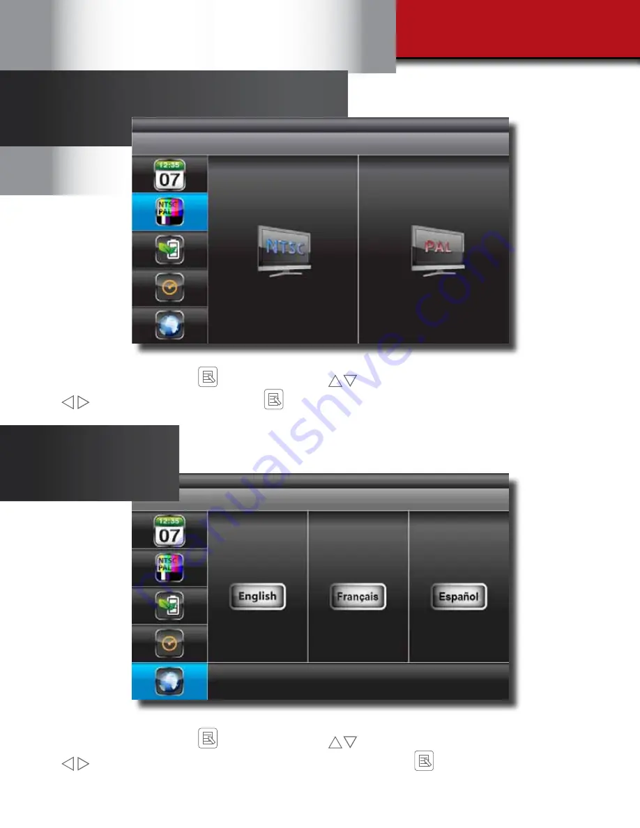
TV Out Setup Menu

Select SYSTEM SETUP, press 

 MENU to enter. Use 

to select TV OUTPUT.

Use 

 to highlight NTSC or PAL. Press 

 MENU to confirm selection. Press ESC to save and exit.

NOTE: Changing the TV system may affect display image scale

Summary of Contents for DWS-401

Page 1: ...USER S MANUAL Model DWS 401 1 Camera Included SECURITY SYSTEM CAMERAS INCLUDED 4gb...

Page 2: ...ngoing effort to constantly improve our products additional features and functions may have been added since that time and on screen displays may change We encourage you to visit our website at www br...

Page 3: ...mera mode 4GB Micro SD Card Included Supports a maximum of 32GB SDHC memory card Simultaneously preview record from all 4 wireless cameras Independent motion detect recording with adjustable mask zone...

Page 4: ...Activation 12 Recorder Setup Menu 13 18 Record Schedule 13 14 Motion Detection Sensitivity 15 Format Memory Card 15 Setup Mask Area 16 Record Time 16 Playback 17 18 System Setup 19 22 Date and Time S...

Page 5: ...e receiving antenna Increase the separation between the equipment and receiver Connect the equipment into an outlet on a circuit different from that of the receiver Consult the dealer or an experience...

Page 6: ...yback Software and Manuals Power Supplies for DVR and Cameras 2 total AV Cable Mounting Hardware 3 screws and 3 plastic anchors per Camera User s Manual 4GB Micro SD Memory Card with Adaptor Brand may...

Page 7: ...ress to confirm selections 4 Navigation Ring Display Switch Channel Menu Cursor Up Playback Fast Forward Display Switch Channel Menu Cursor Down Playback Fast Reverse Display Volume Up Menu Cursor Rig...

Page 8: ...cription 1 Channel Indicator Shows camera channel being viewed 2 Audio Indicator Shows whether Audio is turned On Off for system 3 Signal Indicator Shows status of signal strength 4 Display Mode Shows...

Page 9: ...UTE INSTALLING CAMERAS 1 Select the position for the camera and secure the camera stand Screws and anchors are supplied Use an appropriate screw type for the mounting surface 2 Screw the camera onto t...

Page 10: ...the following sub menu icons Camera Setup Record Setup Event List System Setup Alarm Buzzer Zoom Scan Activated Cameras and Memory Card Overwrite Zoom Main Menu System Setup Main Menu Scan Activated C...

Page 11: ...begin camera pairing Press Pairing Key button on Camera cord Pairing LED on camera will blink once then will begin blinking continuously indicating data transmission is in process System will confirm...

Page 12: ...lighted use to enable or disable camera Press ESC to return to main menu NOTE Ensure the cameras are paired to the receiver for SCAN or QUAD to function properly camera ON can only be selected when ca...

Page 13: ...3 RECORDER SETUP SYSTEM OPERATION 5 RECORDER SETUP MENU Select RECORDER SETUP press MENU key once to enter sub menu Record Setup Main Menu RECORD SCHEDULE Use to select time block Record Schedule Setu...

Page 14: ...n when the sound is muted See Audio Video Recording Caution Statement below The time slot boxes in the diagram above each represent hourly slots e g selecting AM 10 00 means recording will occur from...

Page 15: ...SC to exit NOTE If a new memory card is used then it must be formatted first here before use MOTION DETECTION SENSITIVITY FORMAT MEMORY CARD Recorder Setup Motion Detection Sensitivity Recorder Setup...

Page 16: ...after motion is detected Use to highlight recording period 2 Min 5 Min 10 MIN press MENU to confirm Press ESC to save and exit SETUP MASKING AREA RECORD TIME Masking Area Setup Grid Recorder Setup Re...

Page 17: ...election and enter selected folder PLAYBACK PLAYBACK SYSTEM OPERATION 5 Use to select Hour each block represent one hour time Press MENU to confirm selection and enter selected folder NOTE Each RECORD...

Page 18: ...n full screen 1 4 3 2 Channel 2 playback in full screen 1 4 3 2 Channel 3 playback in full screen 1 4 3 2 Channel 4 playback in full screen Video progress indicator See 2 at right is shown by a series...

Page 19: ...confusion with the time stamps on recorded and currently recording files stop all ongoing recording processes before altering the system time and restart recording using the new settings DATE TIME SE...

Page 20: ...STEM SETUP press MENU to enter Use to select POWER SAVING Use to highlight SCREEN OFF AFTER 5 MINUTES IDLE SCREEN OFF AFTER 10 MINUTES IDEL SCREEN ALWAYS ON Press MENU to confirm selection Press ESC t...

Page 21: ...FF setting in CAMERA SETUP section will affect which camera s can be displayed during IDLE DISPLAY 2 Audio single channel at anytime will be available during QUAD mode by default on channel 1 or the n...

Page 22: ...exit NOTE While SYSTEM RESTORE icon is highlighted the system firmware version will be displayed example VER 11 06 11 21 13 09 TV OUT LANGUAGE SETUP SYSTEM OPERATION 5 TV OUT SETUP NTSC OR PAL TV Out...

Page 23: ...er ON or OFF When motion is detected by a camera then a buzzer sound will be triggered by the monitor ZOOM Zoom Menu Select ZOOM press MENU to enter ZOOM Mode Press MENU again to zoom in 2X When zoomi...

Page 24: ...R either memory card is missing locked or damaged 2 When memory card is full the system will display MEMORY FULL PLEASE FORMAT on the preview screen if overwrite is not enabled SCAN ACTIVATED CAMERAS...

Page 25: ...Indicator Name Description 1 Channel Playback Screen Shows camera channel being viewed 2 Playback Progress Bar Shows progress of playback file 3 Play Shows status of signal strength 4 Pause Shows batt...

Page 26: ...ows 7 is running on your PC please right click on icon 20111027_Sec24 Media Player_v1 0 9 44 and select Run as administrator option first to begin installation Other Windows version will be similar Wi...

Page 27: ...previous recorded files SNX files already stored on your PC NOTE You will first need to save the files from the Micro SD card to the PC Your PC will need to have a Micro SD card reader If your PC only...

Page 28: ...ne of the Video In BNC ports of the DVR Step 3 Connect the AV cable that ships with the Wireless System to the AV Out port on the Wireless System Receiver Then connect the yellow RCA plug to the adapt...

Page 29: ...AND TIME has been set and the Record Schedule setup correctly Ensure the memory card is inserted into DVR and formatted SD Card is full 0 remaining and the unit is no longer record ing MEMORY FULL PLE...

Page 30: ...ity Schedule Record Time Motion Area Cam 1 Cam 2 Cam 4 Cam 3 5 Min 2 Min 10 Min Go Cam 1 Cam 2 Cam 4 Cam 3 Date Time TV Output Language Default Idle Display Power Save PAL NTSC 15 sec 10 sec 5 sec Qua...

Page 31: ...CH Multiple camera mode Language English Spanish French Zoom 2X Digital Zoom Memory Card 4GB Micro SD card included Supports max to 32GB micro SDHC memory card Motion Block Mask 48 8 x 6 grid zones t...

Page 32: ...the users system as a result of installing the software provided This warranty is in lieu of other warranties expressed or implied and BRK neither assumes nor authorizes any person to assume for it an...

Page 33: ...2012 BRK Brands Inc a Jarden Corporation Company NYSE JAH 3901 Liberty Street Road Aurora IL 60504 8122 Phone 630 851 7330 Tech Services 800 323 9005 www brkelectronics com M08 0426 002...

Reviews: