Firman WH03662OF Operator'S Manual Download Page 39

WH03662OF Portable Generator

English                                                                                                                                                  Customer Service: 1-844-FIRMAN1

37

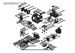
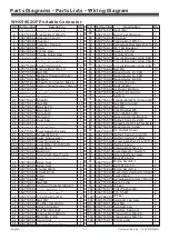
Parts Diagrams - Parts Lists - Wiring Diagram

NO. Part Number

Description

Qty.

1
2
3
4
5
6
7
8
9

10
11
12
13
14
15
16
17
18
19
20
21
22
23
24
25
26
27
28
29
30
31
32
33

33.1
33.2
33.3
33.4

34
35
36
37
38
39
40
41
42
43
44
45
46
47
48
49
50
51
52
53

54
55
56
57
58
59
60
61
62
63
64
65
66
67
68
69
70
71
72
73
74
75
76
77
78
79
80
81
82
83
84
85
86
87
88
89
90
91
92
93
94
95
96
97
98
99

100
101
102
103

103.1
103.2
103.3
103.4

104
105

336718366
336713561
336728304
336728305
336728306
336728307
336418322
330713580
336718371
336718302
336713826
357713569
357713558
336713645
336713613
336713842
336713693
336718371
357713570
336718372
336713611
336718315
336718373
336718374
336718375
336718376
340413002
336418319
393713018
336713547
336713546
336718382
336418305
336713548
336413002
357713600
336713542
336713807
336728308
336728309
336713540
330713509
336713680
336713635
336718314
336428302
336713532
336713533
336713509
336713534
336418307
336718393
336718377
393713046
336718359
336728309
336728310

Flange Bolt M6×35
Flange Bolt M6×25
Inverter Cover I
Inverter
Inverter Cover Ii
Plug
Frame Assy
Choke Knob Assy
Regulation Assy
Flange Bolt M6×12
Cover(lpg Inlet)
Flange Bolt M5×10
Nut M5
Battery Pressing Plate
Battery
Sheath,connecter Black

Sheath,connecter Red
Red Wire
Sheath
Nut M8
Bracket Ii
Bracket I
Isolator 2
Isolator 1
Fuel Cap
Engine Subassembly
Bolt M6×20
Fuel Gauge Display
Screw M5×10
Fuel  Gauge Assy.
Fuel Tank Assy.
Fuel Filter, Wire Mesh
Fuel Tank
Bushing
Grommet, Fuel Tank
Hose,fuel,connector
Hose,fuel
Hose,fuel
Clamp Ø8×6
Clip Ø8.7×8
Pipe
Pipe
Nut M6
Carbon Canister(450cc)
Auspuffdichtung
Flat Washer Ø8
Lock Washer Ø8
Nut M8
Muffler Assembly
Spark Arrester
Muffler Bracket
Flange Bolt M8×20
Bolt St4.2×9.5
Grommet
Control Panel Base

6
4
1
1
1
2
1
1
1

14

1
2
2
1
1
1
1
1
1
1
1

13

1
1
2
2
1
1
4
1
2
1
1
1
1
4
4
1
1
1
6
2
1
1
2
1
1
2
2
2
1
1
1
1
1
1
1

Battery Cable(female 180mm)
Battery Cable(male 250mm)

330713574
336713817
330713651
330713542
330713582
330713614
330713595
330713603
336718378
336713585
336713586
330713596
336713832
380713518
336713588
336418308
357713586
330713630
330713599
336713827
336718345
336713577
336718325
336713579
336718367
336718379
336713575
336713673
336718380
336713674
336713573
336713574
336718368
330713602
336718369
336713815
336418309
336713820
336713821
336713819
336713822
336718381
336713824
336718370
340713002
340728302
336713510
336713556
340728303
340413006
336718313
340713006
336713557
336713561
336713559
336713618

Rectifier
Dual Fuel Module
Charger
Flange Bolt M5×14

DC 10A Breaker
Speed Limiter
Parallel Ports
Circuit Breaker Amp 50A
Circuit Breaker Amp 20A
Circuit Breaker Amp 30A
Nut M4
Receptacle L5-30R
Receptacle 14-50R
Receptacle 5-20R
Control Panel
Multi Meter
Ac Reset Button
Switch, Economy
Switch

Nut M5(ground)
Nut M5
Flat Washer Ø5
Star Washer Ø5
Receptacle Fix Board
Outlet Cover 5-20R

Receptacle & Usb
Dc Outlet Cover
Outlet Cover L14-30R
Outlet Cover TT-30R
Screw&washer Assy M3×6
Outlet Cover
Flange Bolt M4×14
Fuel Selector Switch
Operate Panel Assy
Bolt ST2.9×32
Micro Switch 1
Bolt St2.9×19
Micro Switch 2

Fuel Valve

Axle Comp
Wheel
Flat Washer Ø8
Pin, Shaft
Wheel
Support Leg Assy
Nut M6
Support Leg
Rubber, Support
Flange Bolt M6×25
Flange Bolt M8×16
Pilot Lamp

1
1
1
2

18

1
1
2
1
1
1

10

1
1
2
1
1
1
1
1
1
1
1
2
1
1
1
1
1
1
1
1
2
2
1
1
1
1
1
2
2
1
1
2
2
1
2
2
1
1
2
1
2
2
2
1

NO. Part Number

Description

Qty.

Screw&washer Assy M5×14

Flange Bolt M5×16(ground)

Receptacle DC Lighter Style

Multi-function Switch Seat

Screw&washer Assy M4×20

Summary of Contents for WH03662OF

Page 1: ...P N 336745482 Rev 02 OPERATOR S MANUAL DUAL FUEL INVERTER GENERATOR Record product information to reference when ordering parts or obtaining warranty coverage MODEL NUMBER WH03662OF Rev Level 00...

Page 2: ...e harmful interference to radio communications However there is no guarantee that interference will not occur in a particular installation If this equipment does cause harmful interference to radio or...

Page 3: ...rt This manual contains safety information to make you aware of the hazards and risks associated with generator products and how to avoid them This generator is designed and intended only for supplyin...

Page 4: ...s vapors are extremely flammable which could cause burns or fire resulting in death or serious injury Engine exhaust could cause fire resulting in death or serious injury Hot Surface Muffler could cau...

Page 5: ...may be Federal or State regulations local codes or ordinances that apply to the intended use of the generator Consult a qualified electrician electrical inspector or the local agency having jurisdict...

Page 6: ...ing through any openings If an extension cord running directly into your home is used to power indoor items the operator recognizes that this increases the risk of CO poisoning to people inside the ho...

Page 7: ...age on this page 05 FEATURES AND CONTROLS 1 2 3 4 6 Fuel Select Switch 7 Inverter 8 6 0 Gallon 23L Capacity Fuel Tank Fuel Cap Fuel Gauge Bottle Opener 5 Choke Knob Handle 9 Recoil Starter 10 Battery...

Page 8: ...English Customer Service 1 844 FIRMAN1 06 FEATURES AND CONTROLS...

Page 9: ...English Customer Service 1 844 FIRMAN1 07 FEATURES AND CONTROLS...

Page 10: ...English Customer Service 1 844 FIRMAN1 08 FEATURES AND CONTROLS...

Page 11: ...enerator is overloaded The green AC Power Indicator Light comes on when the engine starts and generates power 6 Overload Indicator Light This light turns ON when the generator is overloaded and will c...

Page 12: ...maximum of 30 4 Amps current may be drawn from this receptacle 16 120V 30A Twist Lock NEMA L5 30R A maximum of 30 Amps current may be drawn from this receptacle 15 Parallel Operation Outlets These out...

Page 13: ...crawlspaces sheds or other partially enclosed spaces even if using fans or opening doors and windows for ventilation Carbon monoxide can quickly build up in these spaces and can linger for hours even...

Page 14: ...able generator at least 5 ft 1 5 m from any structure trees or vegetation over 12 in 30 cm in height Select an outdoor site that is dry and protected from the weather Do not move portable generator in...

Page 15: ...chart to select the proper oil for the outdoor temperature range expected NOTICE Do not attempt to crank or start the engine before it has been properly filled with the recommended type and amount of...

Page 16: ...enough to deactivate the internal low oil level switch Make sure the sump is completely full of oil to the upper limit H Do not operate engine until oil level issue is corrected Contact Firman custom...

Page 17: ...ative main jet and installation instructions can be obtained by contacting Customer Support NOTICE Operation using an alternative main jet at elevations lower than the recommended minimum altitude can...

Page 18: ...CSA B149 1 Natural Gas and Propane Installation Code as applicable If possible the fuel supply connection should be close to the outdoor operating location This will reduce the cost of the flexible fu...

Page 19: ...ll properly charge the battery only when the engine is running The generator cannot be started in Battery Power Saving Mode Turn main fuel selector switch to the off position and back to the GAS or LP...

Page 20: ...engine successfully anytime during the 4 minutes will turn the indicator light OFF See Indicator light Battery Power Saving Mode section for more information 10 Allow portable generator to run at no...

Page 21: ...th regulator to both LPG cylinder and portable generator LPG Hose Connector inlet LPG 4 Fully open the LPG cylinder knob 5 Disconnect all electrical loads from the generator Never start or stop the ge...

Page 22: ...idly 9 For recoil start only Move the choke knob to the RUN position 10 For recoil start only PULL TO RUN Pull the starter cord slowly until resistance if felt and pull rapidly to run the portable gen...

Page 23: ...tion and normally is not an indication of a problem In unusual situations this frost may eventually restrict the flow of LPG gas to the generator resulting in deteriorating performance In these rare s...

Page 24: ...position 2 Start the generator with no electrical load attached 3 Allow the engine to run for several minutes to stabilize 4 Plug in and turn on the first item It is best to attach the item with the l...

Page 25: ...lly NOTICE Storage batteries give off EXPLOSIVE hydrogen gas while charging Do not allow smoking open flames sparks or spark producing equipment in the area while charging WARNING Battery electrolyte...

Page 26: ...ne by moving the choke to the start position Let the generator run at no load for one minute to stabilize internal temperatures of the engine and generator 24 OPERATION 2 Turn the main fuel selector s...

Page 27: ...engine to run for several minutes to stabilize 3 Plug in and turn on the first item It is best to attach the item with the largest load first 4 Allow the engine to stabilize 5 Plug in and turn on the...

Page 28: ...lter New spark plug and clean air filter assure proper fuel air mixture and help your engine run at peak performance and last longer To be performed by knowledgable experienced owner or by authorized...

Page 29: ...longed or repeated skin contact with used motor oil Used motor oil has been shown to cause skin cancer in certain laboratory animals Thoroughly wash exposed areas with soap and water KEEP OUT OF REACH...

Page 30: ...a clean cloth b Saturate foam air filter element with clean engine oil and squeeze in a clean cloth to remove excess oil Spark Plug Maintenance Changing the spark plug will help your engine start easi...

Page 31: ...tates or federal jurisdictions may have similar laws reference Federal Regulation 36 CFR Part 261 52 29 Maintenance Storage A Spark plug B Spark plug boot A B c Inspect spark plug for damage and clean...

Page 32: ...arrester in the muffler and attach with the screws NOTICE Failure to clean or replace spark arrester may result in decreased engine performance GENERATOR MAINTENANCE Make certain that the portable gen...

Page 33: ...Cover the post with boots 9 Install the spark plug wire onto spark plug A M6X12 Battery Charging The battery powers the starter motor and control module This portable generator is equipped with an aut...

Page 34: ...wn 3 There is no need to drain gasoline from the generator fuel tank if fuel stabilizer is added 4 FUEL STARVATION If you elect to drain fuel tank move generator outdoors Once fuel tank is drained tur...

Page 35: ...tank and carburetor fill with fresh gasoline 6 Connect wire to spark plug 7 Replace spark plug 8 Drain gas tank and carburetor fill with fresh gasoline 9 Wait 5 minutes and re crank engine 10 Contact...

Page 36: ...Air Cleaner P T O Shaft Rotation 120V Digital Single 1 Single Cylinder 4 Stroke OHV Air Cooled 208cc Breakless Ignition Type Flywheel Magneto Unleaded Automotive Gasoline 6 U S Gallons 23L 20 3 oz 0...

Page 37: ...PARTS DIAGRAM AND PART LIST WH03662OF PARTS DIAGRAM English Customer Service 1 844 FIRMAN1 35...

Page 38: ...208cc ENGINE PARTS DIAGRAM English Customer Service 1 844 FIRMAN1 36...

Page 39: ...ck Washer 8 Nut M8 Muffler Assembly Spark Arrester Muffler Bracket Flange Bolt M8 20 Bolt St4 2 9 5 Grommet Control Panel Base 6 4 1 1 1 2 1 1 1 14 1 2 2 1 1 1 1 1 1 1 1 13 1 1 2 2 1 1 4 1 2 1 1 1 1 4...

Page 40: ...t M8 32 Seal Oil Cover crankcase Oil Dipstick Assy Bearing Crankcase Assy Woodruff Key Locating Pins Gasket Crankcase Flange Bolt M6 12 Sensor Engine Oil Crankcase Subassembly Bolt Drain Plug 33672354...

Page 41: ...336723557 336728302 336723558 336723559 336723560 336723561 336713527 336718308 336418315 336428304 335425590 340418306 Bolt M4 14 Step Moter Assy Bolt M3 6 Step Moter Cover Gasket Air Cleaner Choke L...

Page 42: ...English Customer Service 1 844 FIRMAN1 40 Parts Diagrams Parts Lists Wiring Diagram Wiring Diagram...

Page 43: ...ercial industrial use Transportation charges on product submitted for repair or replacement under this warranty are the sole responsibility of the purchaser This warranty only applies to the original...

Page 44: ...ct Information You may contact FIRMAN at Address Firman Power Equipment Inc Attn Customer Service 8716 W Ludlow Dr Suite 6 www firmanpowerequipment com Peoria AZ 85381 We are FIRMAN POWER And we are h...

Page 45: ...a failure under warranty of any warranted part MANUFACTURER S WARRANTY COVERAGE The exhaust and evaporative emissions control system on your is warranted for two years If any emissions related part o...

Page 46: ...manifold Air cleaner 5 Crankcase breather assembly including Breather connection tube 6 Fuel tank evaporative emission control system including Purge valves Carbon canister Vapor hoses and fitting cla...

Page 47: ...l rights reserved Any reprinting or unauthorized use without the written permission is expressly prohibited TM FIRMAN POWER EQUIPMENT INC 8716 W LUDLOW DR SUITE 6 PEORIA AZ 85381 1 844 347 6261 WWW FI...

Reviews: