background image

GLADIUS SMART System manual version 1.4 


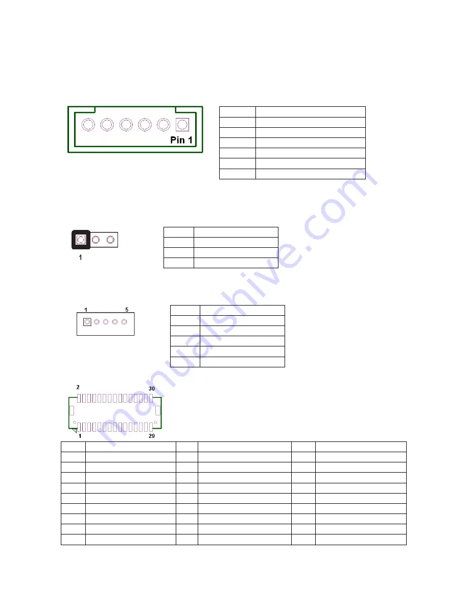
4. KB_MS2 (PS/2 Keyboard and PS/2 Mouse) 


5. LVDS_PWR1 (LVDS 3V/5V selection)  


6. INV_BRIG1 (Inverter with Box-header ) 


7, LVDS 18 bit Connector 


Pin


Definition


Pin


Definition


Pin


Definition


GND 

12 

Backlight Enable 

23 

LVDS Clock+ 

NC 

13 

GND 

24 

Backlight 5V 

EDID Data 

14 

Backlight Controller 

25 

GND 

GND 

15 

Data1+ 

26 

GND 

EDID Clock 

16 

GND 

27 

Data2- 

NC 

17 

Data1- 

28 

LVDS Power 3.3V 

GND 

18 

GND 

29 

Data2+ 

NC 

19 

GND 

30 

LVDS Power 3.3V 

Data0+ 

20 

Backlight 5V 


KB_MS2:


Pin


Definition


GND 

KDAT 

F_KDAT 

KCLK 

F_KCLK 

5V 


LVDS_PWR1: Default:

 1-2


Pin


Definition


3.3V 

DC input 

5V 


INV_BRIG1:


Pin


Definition


12V DC out 

12V DC out 

GND 

Backlight Controller 

Backlight Enable 


Summary of Contents for Gladius Smart

Page 1: ...U Us se er r s s M Ma an nu ua al l Version 1 4 Copyright 2011 All rights reserved All other brand names are registered trademarks of their respective owners Gladius Smart 15 All in one POS PC...

Page 2: ...on provided in this manual is intended to be accurate and reliable However FIRICH ENTERPRISES CO LTD assumes no responsibility for its use nor for any infringements upon the rights of third parties wh...

Page 3: ...on it Do not place anything over the power cord 10 All cautions and warnings on the equipment should be noted 11 If the equipment is not used for a long time disconnect it from the power source to avo...

Page 4: ...ntains information protected by copyright No part of this manual may be photocopied or reproduced in any form without prior written consent from the manufacturer 2011 All rights reserved The software...

Page 5: ...stallation 18 C Ch ha ap pt te er r 3 3 1 19 9 Software Setup 19 Please follow this installation sequence accordingly 21 Intel Chipset Driver Installation for Windows XP 22 VGA Driver Installation 24...

Page 6: ...ioning normally 52 MCR is not functioning properly 52 VFD Display is not functioning properly 53 LAN is not functioning properly 53 COM1 and COM2 are not functioning properly 53 Cash Drawer Port is no...

Page 7: ...efficiently Housing The solid aluminum housing dissipates the heat inside the system and makes it a perfect fan less solution additionally it also assures the compliance to EMI radiation testing Disp...

Page 8: ...GLADIUS SMART System manual version 1 4 Detachable Stand Optional LCM A Quick Tour of GLADIUS SMART Before you start please take a moment to become familiar with GLADIUS SMART...

Page 9: ...GLADIUS SMART System manual version 1 4 Identification Devices 1st Display Back I O VFD or Monitor pole stand Power LED HDD Wireless Module Power Adapter Power Cable LCM...

Page 10: ...GLADIUS SMART System manual version 1 4 GLADIUS SMART Dimension...

Page 11: ...KB MS PS 2 Connector The K B or Mouse port for an external keyboard COM1 COM2 RS232 Connector The serial ports COM1 COM2 can be used to connect serial devices VGA 15 PIN VGA Connector The Ext VGA por...

Page 12: ...4V power out support Line Out Earphone Connector The audio port is for speakers Mic In Optional Microphone Connector This is used for allowing usage of microphone LPT1 26 PIN SCSI II Connector The par...

Page 13: ...are Chapter 1 Provides an introduction to Gladius Smart and this manual Chapter 2 Provides all necessary information for all hardware setup Chapter 3 Provides the necessary information for installing...

Page 14: ...power supply is disconnected when making any hardware changes to Model GLADIUS SMART Access to jumper setting and RAM 1 Turn off system power 2 Remove four screws to detach the panel 3 Pull up the pan...

Page 15: ...tor to terminal 2 5 Hard Disk Drive Installation 1 Turn off system power 2 Open the cover on the left of terminal and turn off system power 3 Remove one screw 4 Pull out whole HDD bracket 5 Mount SATA...

Page 16: ...1 Turn off system power 2 The MCR socket can be found on the right side of terminal 3 Attach the MCR Assembly to terminal and connect the MCR cable to the MCR socket 4 Lock MCR to terminal with 2 scre...

Page 17: ...UserManual_TM970001 pdf VFD Customer Display Installation 1 Turn off system power 2 Important make sure that the jumpers on the I O board are set correctly It s important to note that the supply volta...

Page 18: ...pplication Plug cash drawer cable into cash drawer port Note If the cash drawer cannot be detected by the system please refer to troubleshooting Up to two cash drawers may be driven from this port Dri...

Page 19: ...The DVD has all the necessary drivers to setup Model GLADIUS SMART Please insert the DVD into DVD ROM Installation will start automatically through detecting your terminal s BIOS there will be a menu...

Page 20: ...GLADIUS SMART System manual version 1 4 2 Choose which driver you want to install but please read the installation sequence carefully...

Page 21: ...to follow our sequence is that IRQ settings will be changed by Windows XP to non supported values and you may encounter unnecessary problems later Note When installing the IEGD driver for VGA under PO...

Page 22: ...m manual version 1 4 Intel Chipset Driver Installation for Windows XP Step 1 Find the setup file through index Step 2 Click Next Step 3 Read the License Agreement and click Yes to continue Step 4 Clic...

Page 23: ...GLADIUS SMART System manual version 1 4 Step 5 Click Next to continue Step 6 Click Finish to complete setup...

Page 24: ...GLADIUS SMART System manual version 1 4 VGA Driver Installation Step 1 Find the setup file through index Step 2 Click Next to continue Step 3 Read the License Agreement and click Yes to continue...

Page 25: ...GLADIUS SMART System manual version 1 4 Step 4 Click Next to continue Step 5 Click Next to continue...

Page 26: ...GLADIUS SMART System manual version 1 4 Step 6 Click Finish to complete setup Audio Driver Installation Step 1 Find the setup file through index Step 2 Click Next to continue...

Page 27: ...GLADIUS SMART System manual version 1 4 Step 3 Click Finish to complete setup Lan Driver Installation Step 1 Find the setup file through index Step 2 Click Next to continue...

Page 28: ...GLADIUS SMART System manual version 1 4 Step 3 Click Next to continue Step 4 Click Finish to complete setup...

Page 29: ...version 1 4 ELO Touch Tools Installation ELO Touch Tools Installation for Windows XP Windows Vista Windows 7 1 Find the setup file through index Tools 2 Open SW601379_TETouch_5 2 0 exe 3 Click OK to...

Page 30: ...GLADIUS SMART System manual version 1 4 4 Install Elo Touch drivers and utilities 5 Tick the Install USB Touchscreen Drivers and click Next to continue...

Page 31: ...GLADIUS SMART System manual version 1 4 6 Read the License Agreement and click Yes if you accept it 7 Select Auto detect Elo devices and click Next...

Page 32: ...SMART System manual version 1 4 8 Click Calibrate Elo Touchscreen monitors 9 Using a soft tip object such as finger to calibrate the touch screen Red bull s eye will pop up three time on different po...

Page 33: ...ontrol Panel This section explains the different options in the ELO control Panel General tab The General tab allows you to calibrate the touch screen with the Align button Mode tab The Mode tab allow...

Page 34: ...GLADIUS SMART System manual version 1 4 Change cursor properties Enable or disable right mouse button utility Sound tab The Sound tab allows you to To change sound properties for ELO touch tools...

Page 35: ...GLADIUS SMART System manual version 1 4 Properties tab The Properties tab allows you to View Controller Information About tab The About tab displays Information about ELO Touch systems...

Page 36: ...less LAN Driver Installation 1 Find the setup file through index Tools 2 Open WiFi 118E exe 3 Click Next and start the installation 4 Select Install driver and Ralink WLAN Utility 5 Select Ralink Conf...

Page 37: ...GLADIUS SMART System manual version 1 4 6 Select Install 7 Click Finish...

Page 38: ...GLADIUS SMART System manual version 1 4...

Page 39: ...ze Resolution 15 LED 1024 x 768 100K hrs Option CCFL 1024 x 768 30K hrs Brightness 450 nits Option 250 nits Touch Screen 5w Resistive touch Serial Port 2 x COM ports DB 9 male 1 x COM port RJ 45 for 1...

Page 40: ...rnal Power Adaptor Construction Whole Aluminum Housing Color ID Black Optional LCM Use COM6 with 5V as default Thermal Conditions Fanless Thermal Design Operating Temperature 0 40 O S Supported Window...

Page 41: ...1 1 port D USB 2 0 1 1 Port E COM2 12V_OUT Pin Definition 1 12V 2 GND COM4_USB1 Pin Definition 1 RI 5V 12V 2 CTS RTS 3 GND 4 RTS GND 5 DTR 6 DSR 7 TXD 8 RXD COM4_USB1 USB_LAN1 Pin Definition 1 USB 5V...

Page 42: ...5 GND 6 GND 7 GND 8 GND 9 VCC 5V 10 GND 11 NC 12 DDC Data 13 H SYNC 14 V SYNC 15 DDC Clock USB_LAN1 Connection Speed LED State Description Orange Speed 1 Gbps Green Speed 1 00 Mbps State Description...

Page 43: ...16 INIT 4 PD2 17 SLIN 5 PD3 18 GND 6 PD4 19 GND 7 PD5 20 GND 8 PD6 21 GND 9 PD7 22 GND 10 ACK 23 GND 11 BUSY 24 GND 12 PE 25 GND 13 SLCT Pin Definition 1 Keyboard Data 2 Mouse Data 3 GND 4 Mouse Cloc...

Page 44: ...l internal use This connector is reserved for future use 2 CPU_FAN CPU FAN 3 SYS_FAN System FAN CPU_FAN Pin Definition 1 GND 2 12V RPM control 3 RPM detect 4 RPM control SYS_FAN Pin Definition 1 GND 2...

Page 45: ...2 NC 13 GND 24 Backlight 5V 3 EDID Data 14 Backlight Controller 25 GND 4 GND 15 Data1 26 GND 5 EDID Clock 16 GND 27 Data2 6 NC 17 Data1 28 LVDS Power 3 3V 7 GND 18 GND 29 Data2 8 NC 19 GND 30 LVDS Po...

Page 46: ...display JCOM6 is always set as 1 2 short for built in LCM Default 1 2 Pin Definition 1 RS232 2 UART RXD 3 RS422 4 UART RXD 5 RS485 6 UART RXD JRS2 Default 2 3 short Pin Definition 1 RS485 D 2 COM2 Pin...

Page 47: ...NCTS4 2 NRTS4 3 L3 4 L5 5 RI4 1_5V 12V_F 6 GND PS JCOM4 is always set as 5 6 short for VFD display use 12 JFRONT Front Panel Connector with Box header Pin Definition Pin Definition 1 Stand by LED 2 P...

Page 48: ...USB Dx 4 USB Dy 5 USB Dx 6 USB Dy 7 GND 8 GND 9 NC 10 NC F_USB3 USB Pin header Pin Definition Pin Definition 1 USB Power 5V 2 USB Power 5V 3 USB Dx 4 NC 5 USB Dx 6 NC 7 GND 8 GND 9 NC 10 NC 14 USB_PW...

Page 49: ...8 Line In_L 9 Amplifier Out_L 10 Line In_JD 11 GND 12 MIC_JD 16 VGA2 VGA Connector with Box header Pin Definition Pin Definition 1 V SYNC 2 H SYNC 3 GND 4 GND 5 RED 6 GND 7 GREEN 8 DDC Clock 9 BULE 1...

Page 50: ...SMART System manual version 1 4 19 LCDPWR_CON LCD Power ON OFF 20 BKLTEN_CON Back light Inverter Enable Disable Default 1 2 Open ON Short 1 2 OFF Open 1 2 Default 1 2 Open Enable Short 1 2 Disable Op...

Page 51: ...ould be defective C Check CMOS setup set SATA HDD to Auto detects Touch Panel does not Work A Check CMOS settings COM port needs to be Enabled And check the IRQ from the MB manual B Check if the ELO d...

Page 52: ...ould be defective PS 2 Keyboard is not functioning normally A Make sure the keyboard is properly connected to the PS 2 keyboard port before the system is powered up If the keyboard is connected after...

Page 53: ...oard COM4 I O chips could be defective LAN is not functioning properly A Check if the LAN driver is installed properly Please refer to the LAN driver installation B Check if there are any IRQ conflict...

Reviews: